Arduino are single-board microcontrollers that are easily programmable through a USB connection. They are used with electronics to design embedded system prototypes, the Internet-of-Things (IoT), and electronic gadgets.
Much like other microcontrollers, Arduino provides software-backed computing and embedded control to basic electronics applications. That means getting started with Arduino is no different than with other systems.
The setup
While working on Arduino, users can learn and work on electronics. To begin, an electronics workbench is recommended and a PC or laptop. For tips on setting up an electronics workbench, check out this tutorial: Beginners Guide To Set up An Electronics Lab.
Ideally, these tools or equipment will also be needed:
1. Breadboards, Micro or Mini Breadboards – to prototype circuits.
2. Breadboard Power Supply (Optional) – to supply power to breadboards through adaptor or USB.
3. Male-to-Male Jumper Wires – to make connection of Arduino pins with Breadboard and make connections between components on Breadboard.
4. Connecting Wires – to make connections between components on Breadboards.
5. Bug Strip Connectors – to make connections of PCB modules on breadboard.
6. Wire Stripper – to strip connecting wires.
7. Wire Cutter – to cut wires and trim bug strip connectors.
8. Set of Tweezers – to hold components, and place or remove components on breadboard. It will be best to get a set of electrostatic tweezers.
9. Precision Screwdrivers – to calibrate pots, remove components on breadboards etc.
10. Protoboards or PCBs – to make permanent a breadboard circuit. Perf Boards or Strip boards can be used to quickly finalize a prototype design. For better finishing, a PCB can be designed for the prototype using a PCB design software and the entire circuit can be transferred to it.
11. Soldering Iron and Solder – to solder components on Protoboards or PCBs, or to solder bug strip connectors on PCB modules. Leaded or Lead-free solder can be used. Though leaded solder is easy and handy to use, lead-free solder is safe for health.
12. Soldering Pump – to fix soldering errors.
13. PCB Holder – to hold PCBs while soldering.
14. Tip Tinner – to keep soldering tip clean.
15. Copper Sponge – To clean soldering tip.
16. Assortment Kit of 1/4-Watt resistors, electrolyte and ceramic capacitors, potentiometer and variable resistors, and push buttons
17. LEDs
18. Multimeter – to measure voltage, current and resistance.
19. Bench Power Supply (Optional) – to power breadboard circuits. The breadboard circuits can be supplied 3.3 and 5V power from Arduino. For a power supply greater than 5V, a battery pack in with voltage regulator ICs can be used. Power adaptors or a USB power supply with breadboard power supply can also be used to power breadboard circuits that require a supply of greater than 5V.
In addition to the above tools, users will also need:
1. Arduino boards of choice
2. USB cable for programming Arduino boards
3. Computer (PC or Laptop) to run Arduino IDE or any other competitive programming environment.
4. Power supply for Arduino – Arduino boards can be supplied power through a USB, power adaptor, or battery pack. These boards have an on-board voltage regulator, so there’s no need of external voltage regulator.
For advanced testing of circuits and signals, users may have oscilloscope and logic analyzer. However, these are unnecessary. It’s possible to get display devices, sensors, actuators, application-specific modules, and Arduino shields based on preferences.
Here are some commonly used display devices in embedded electronics and gadgets:
- LED(s)
- RGB LED(s)
- SSD(s)
- LED Boards
- Character LCD
- Graphic LCD/OLED
- Touch Screens
Here are the more popular sensors popular for electronics hobbyists:
- Thermistor
- TMP36 Temperature Sensor
- LM35 Temperature Sensor
- DHT-11/DHT-22 Digital Temperature Sensor
- Analog Microphone
- Digital Microphone
- Photoresistor (LDR)
- GUVA – S12SD Ultraviolet Light Sensor
- TCS34725 RGB Color Sensor
- Passive Infrared (PIR) Sensor
- BMP-080/BMP180/BMP280 Barometric Pressure Temperature and Altitude Sensor
- MCP9808 High Accuracy I2C Temperature Sensor
- ADXL335 Accelerometer Sensor
- HC-SR04 Ultrasonic Distance Sensor
- IR Sensors
- Active/Passive Buzzers
- Soil Moisture Sensor
- MPU-6050 3-Axis Accelerometer & Gyro Sensor
- MQ-9, MQ-8, MQ-7, MQ-6, MQ-5, MQ-4, MQ-3, MQ-2, MQ 135 Gas Sensors
- Proximity Sensors
- PH Sensors
- Load Cells
These actuators typically used for controlling mechanical systems:
- Brushed DC Motors
- Brushless DC Motors
- Micro Gear Motors
- Servo Motors
- Stepper Motors
- Gear Motors
- AC Motors
- Linear Actuators
- Air Pumps
- Water Pumps
Some of the popular application-specific modules include the following –
- RFID Readers
- Fingerprint Scan Modules
- Camera Modules
- GSM-GPRS Modules
- GPS Modules
- QR Code Scanning Modules
- RTC DS1307
- Wi-Fi Modules
- Bluetooth Modules
Some of the popular Arduino Shields include:
- 1Ethernet Shield
- Relay Shield
- L293D Motor Driver Shield
- GPS Shield
- Data-logging Shield
- CAN Shield
- Proto Shield
There are other thousands of sensors, sensor modules, actuators, application-specific modules, and custom-build shields. Engineers and hobbyists can choose based on the project requirement.
Most of the sensors or sensor modules operate on TTL voltages, which means they can easily interface with Arduino boards. The sophisticated modules, such as RFID or GPS, have serial communication interfaces that also communicate effortlessly with Arduino boards. Several actuators operate on higher voltages, however, which may lead to damaged control circuitry. So, they typically require additional external circuits or shields when controlled by the Arduino.
The Arduino shields are designed to fit in Arduino boards and may be providing a connectivity solution or ready-to-use embedded solution. Before beginning an Arduino journey, a few pre-requisite skills are necessary.
For example:
- Assembling and prototyping circuits on Breadboards.
- Familiar using Multimeter to measure voltage, current, and resistance.
- Comfortable using Multimeter to test basic electronic components, such as testing continuity, diodes, and transistors.
- Soldering components and connectors on Protoboards and PCBs.
These skills are unnecessary but will provide an advantage:
- Designing PCBs using a PCB design software
- Etching and making PCBs
- Using Oscilloscopes and Logic Analyzer for testing circuits and signals
Arduino UNO
There are many Arduino and Arduino Pro boards. The most documented and used board is Arduino UNO. “Uno” means one in Italian and it is the first-ever Arduino board designed and supported by the company.
UNO uses AVR ATmega328P as the sitting microcontroller, which is clocked by a 16 MHz ceramic resonator. The major components on this microcontroller board are indicated in this image.
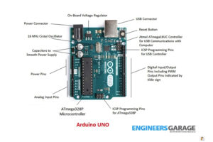
Arduino UNO has two microcontrollers on-board, the ATmega328P and ATmega16UC. The Atmel ATmega16UC is an SMD microcontroller that’s only used to manage USB communications between ATmega328P and the computer. It cannot be used for controlling embedded electronics.
The Arduino can be easily programmed via USB cable using Arduino IDE. It also has ICSP header pins for programming both controllers using an external programming device. The ATmega32P on Arduino UNO can be replaced if damaged. It should be noted, however, that the replacement microcontroller may not come with a bootloader. In that case, the bootloader can be burned to the controller from Arduino IDE. The ATmega328P is clocked by a 16MHz crystal.
The board can be powered by USB cable, AC-to-DC adaptor, or battery pack. The same USB cable that’s used to program the Arduino also supplies power to it. So, Arduino can be powered through a USB of a computer while programmed and the design is under testing.
Once programmed, it will need to be installed elsewhere. For instance, it can be powered through an AC-to-DC adapter or a battery pack. The adaptor or battery pack can be connected through a power connector of the board. The Arduino comes with an on-board voltage regulator, so it requires zero external voltage regulation circuit or device if it’s powered by a battery pack.
The Arduino UNO requires an operating voltage of 5V, although it can be input in a DC voltage ranging from 7 to 12V. It’s highly recommended to supply a voltage to the Arduino that’s close to its operating voltage, however, as any excess power supply will be wasted by the on-board voltage regulator.
In addition to the voltage regulator, Arduino has two capacitors to clean up any excess voltage.
Arduino UNO is equipped with these hardware features:
1. Digital Input/Output – Arduino UNO has 14 digital I/O pins. Its analog input pins can also be used for digital I/O. So, there are 20 pins on UNO that can be used for digital input and output. All of these pins operate on TTL logic. The pins sense any input signal level between 2 and 5V as logical HIGH and any input signal level between 0 and 0.8V as logical LOW. Similarly, the pins output a voltage between 2.7 to 5V for logical HIGH and a voltage between 0 to 0.5V for logical LOW. Unconnected pins on the Arduino are in a hanging or floating state.
2. Analog Output – Arduino does not output any analog signal. Instead, it can output Pulse Width Modulated (PWM) signals that approximate to analog signals. Out of the 14 digital I/O pins, six pins (marked by tilde sign) can output PWM signals on the UNO. These pins are connections to six PWM channels of ATmega328P microcontroller.
3. Analog Input – There are six Analog Input pins on Arduino UNO. These pins can be used to sense analog voltages from sensors and sensor modules. The ATmega328P has 8-channel, 10-bit ADC, so the pins can sense analog voltages at 10-bit resolution.
4. Communication Interfaces – The ATmega328P microcontroller supports programmable serial USART (for peer-to-peer serial communication with a single device), two-wire serial interface (I2C/TWI for half-duplex serial communication with multiple devices) and master/slave SPI serial interface (for full-duplex serial communication with multiple devices). The digital I/O pins can also be used for peer-to-peer serial communication using a software serial that emulates the functioning of a hardware serial port.
5. ATmega328P Built-in Features – The ATmega328P microcontroller housed in Arduino UNO is a RISC (Reduced Instructions Set Computer) with an instruction set of 131 instructions, most of which have single-clock execution. It has 32, 8-bit registers and an On-chip, two-cycle multiplier. The microcontroller has 32 Kb in-system self-programmable flash memory that supports 10,000 write/erase cycles. It has 1Kb EEPROM that supports 100,000 write/erase cycles and 2Kb SRAM. The controller has two 8-bit Timer/Counters with separate prescaler and compare mode; one 16-bit Timer/Counter with separate prescaler, compare and capture mode; programmable watchdog timer with a separate On-chip oscillator, On-chip analog comparator and support for external interrupts at two pins.
Fritzing
Fritzing is an open-source hardware initiative that allows documenting prototypes. It can be used to design paper sketches, schematics, and PCB layouts of electronic circuits including circuits that involve Arduino. Once a design is final on Arduino, users can either document or make it permanent. It’s quite handy to design paper sketches and schematics using Fritzing.
Interestingly, the application simultaneously generates the PCB layouts as well. The final designs can be transferred to protoboards or PCBs as required.
Arduino IDE
Arduino became so popular, thanks to two of its aspects:
1. The ease of uploading programs to the microcontroller via a USB cable
2. A free programming environment
This means even novice or non-engineers can productively use Arduino. Its programs can be written on any text editor or programming environment, provided they are saved as “.ino” files. The Arduino programs are called sketches as they’re meant as temporary firmware programs that can be replaced by others.
In fact, the Arduino can be loaded with sketches thousands of times. ATmega328P supports 10,000 write/erase cycles of flash memory. The ideal editor and programming environment for programming Arduino is the Arduino IDE.
The setup for Arduino IDE can be downloaded from the official website of Arduino (arduino.cc). The IDE is available for Microsoft Windows, Mac OS X, and Linux platforms. After installing the IDE, when it is launched, it looks like this…
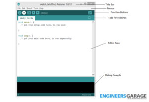
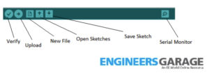
At the top, it has main menus. Below the menus, there are function buttons, which serve to verify the sketch for syntax errors, upload a sketch to Arduino, create a new sketch, open or save a sketch, or open the serial monitor.
There’s also an editor area where users can write their Arduino sketches. At the bottom, there’s a debug console, where messages and errors are displayed when verifying or uploading the sketch.
 In the files menu, the most important one is the preferences:
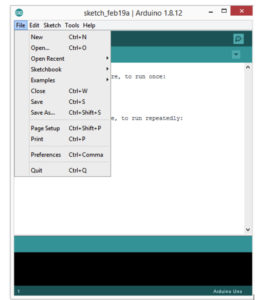 In the preferences, users can:
- Choose a storage location for the sketches
- Set the editor language, font size, and interface scale
- Pick a theme for the IDE
- Select the output on compilation and upload via the debug console
- Decide on the type of compiler warnings to be shown in the debug console
- Use the checkboxes to display line numbers, enable code folding, verify code after upload, use the external editor, check for updates via the startup, save when verifying or uploading, or use the accessibility features.
At the bottom, users can specify URLs for additional board managers.
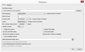 If “display line numbers” is checked, line numbers will be visible in the editor area. It’s recommended this checkbox is selected as it will track programming errors by the line numbers. If “enable code folding” is checked, functions can be minimized in the editor area. This feature is useful to view the relevant parts of code. If “use external editor” is checked, sketches can be written using an external text editor, such as sublime text.
“Verify code after upload” should be checked as it will verify if the program is properly uploading to the microcontroller. If “Save when verifying or uploading” is checked, the sketch will automatically be saved when it is uploaded or verified, which is important.
In the network tab of the preferences, users can also specify network settings so that Arduino IDE can connect with the Internet. By default, Arduino’s auto-detect proxy settings for Internet connectivity are on. Through the file menu, users can also access the sketchbook (this is the folder where the sketches are saved) and several sketch examples.
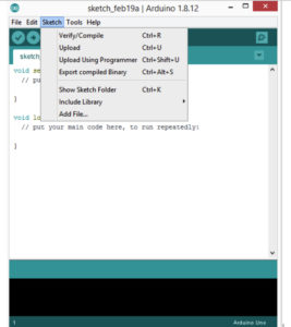
The edit menu has all of the options to edit code in the editor. The keyboard shortcuts for all of these editing operations are also indicated in the menu buttons. In the sketch menu, buttons to verify/compile sketch, upload sketch, upload using programmer, export compiled binary, show sketch folder, add file, and include library submenu are available. Simply open the library manager from the ‘”Include library” submenu and search for libraries if available for a component or solution when required.
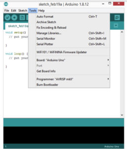
The tools menu has lots of useful features. Using “Auto Format,” users can automatically indent code. The “Archive Sketch” saves the sketch to an archive. If copying code from other sources, the “Fix Encoding & Reload” button will fix any encoding problems due to the code being written in a different programming environment.
From the tools menu, users can also open a serial monitor or serial plotter. It’s possible to select the target Arduino board. By default, the IDE automatically detects the board when it’s connected to the computer via a USB cable.
In the tools menu, it’s also possible to select the port that the Arduino board is connected to. By default, this is also automatically detected by the IDE when the Arduino board is connected to a computer. The tools menu also lets users select a programmer if uploading sketches through an external programming device.
To write a new sketch, it’s necessary to first create a new file. You can write the Arduino code and save it as “.ino file.” Any programming errors can be detected by pressing the “Verify” function button.
To upload the sketch to a target board, simply connect the board via a USB cable and click on the “Upload” function button. As the sketch will be uploaded on a target board, it will start executing. The boards can be reset to the start of the program execution by pressing the reset button on them.
The datasheets
While working on Arduino, you will be experimenting on a number of components and modules. To start with any electronic component or module, the first thing is to check out its datasheet. The datasheets are well-documented sources of information about a component.
It’s essential to look for the operating requirements, functioning, and applications of a component from its datasheet before using it in a circuit.
The Arduino UNO has ATmega328P as the sitting microcontroller. Start the habit of reading datasheets from the datasheet of ATmega328P microcontroller itself. Simply download the datasheet and check out the microcontroller specifications, operating conditions, and features. It’s interesting to inspect the built-in registers of the ATmega328P. And yes, there are 32 8-bit registers in ATmega328P.
In the next tutorial, we will look at the basic structure of Arduino sketches and get through the basics of embedded C for the Arduino platform.
You may also like:


Filed Under: Arduino Projects, Featured Contributions, Tutorials
Log in to leave a comment:
Lost your password?
Don't have an account? Register here