Seven Segment Displays are commonly used for displaying numeric information. These displays can be seen at airports, railway stations, and bank counters. In this project, Bluetooth is used to send data for display on Seven Segment Displays. The project allows sending a number with or without the decimal point from an app on the Android phone to the projecting device. The projecting device receives the number through Bluetooth and displays it on the Seven Segment displays.
The Bluetooth Serial monitor app is used for sending the number from Android phone to the device. The Android phone should be paired with the HC-05 Bluetooth module interfaced in the project. Once the Android phone is paired with the Bluetooth module, the Bluetooth Serial monitor app can be used to send data serially to the device.
On the projecting device, there are 8 seven segment displays connected by the technique of Multiplexing. In the technique of Multiplexing, the common pin of the SSDs are not hard wired to VCC or ground depending upon the type of SSD but the common pin of the SSDs (Like Anode pin of Common Anode SSDs or Cathode pin of Common Cathode SSDs) are connected to the microcontroller pins. The respective LED pins of the SSDs are connected to same microcontroller pins like LED ‘a’ of all the SSDs is connected to one and same microcontroller pin, LED ‘b’ of all the SSDs is connected to other but same microcontroller pin and so on. Every SSD is programmatically selected at a time and LEDs are switched ON or OFF to display the desired number.
The project is built on Arduino UNO and the Arduino sketch manages to read number passed through Bluetooth and display it with the decimal point on SSDs by multiplexing technique. The Arduino sketch is written on Arduino IDE and burnt to the board using AVR Dude.
Fig. 1: Prototype of Bluetooth Controlled Seven Segment Display
Components Required:
1) Arduino UNO
2) 7-Segment display – 8 pcs
3) Bluetooth Module HC-05
4) Connecting Wires
5) Any Android Phone
Software Tools Required –
1) Arduino IDE
2) AVR Dude
3) Bluetooth Serial Monitor App
Block Diagram –
Fig. 2: Block Diagram of Bluetooth Controlled Seven Segment Display
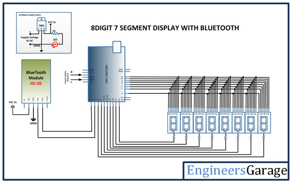
Circuit Connections –
The Arduino UNO receives the data from the Bluetooth module and controls the seven segment displays. The Arduino board has the Bluetooth module and the SSDs interfaced in the following manner –
HC-05 Bluetooth Module – HC-05 Bluetooth module is serial port protocol module. It operates on ISM band 2.4GHz with V2.0+EDR (Enhanced data date). It can work in both Master and slave modes. The Bluetooth module has six pins – Enable, VCC, Ground, Transmit Data (TxD), Receive Data (RxD) and State. The Enable and State pin are unused and so not connected in the circuit. The VCC and Ground pins are connected to the common VCC and Ground. The TxD and RxD pins of the module are connected to the pins 2 and 3 pins of the Arduino board respectively.
Seven Segment Displays – There are 8 seven segment displays connected in the circuit through multiplexing technique. The ‘a’, ‘b’, ‘c’, ‘d’, ‘e’, ‘f’, ‘g’ and ‘.’LEDs of all the SSDs are connected to the pins 4, 5, 6, 7, 8, 9, 10 and 11 of the Arduino board respectively. The common pins of the SSDs are connected to pins A0, A1, A2, A3, A4, A5, 12 and 13 of the Arduino board. The LEDs on the seven segment display are operated in the following fashion to display different digits –
Fig. 3: Table listing LED status of Seven Segment Display for display decimal digits
Fig. 4: Pin Diagram of Seven Segment Display
Learn more about the seven segment displays and learn how they work. Since the project is built on Arduino, the LEDs of the seven segments need not be controlled individually. There is a standard library available for handling multiplexed seven segments with the Arduino.
Android Phone – Any Android phone can be used for sending the number to be displayed on SSDs. The android phone connects with the circuit on Bluetooth. It should be paired with the Bluetooth module. The Bluetooth module used in this project had a Mac address of 05 20:15:01:30:17:25 for its unique identification and had a password 1234 for pairing. The other Bluetooth modules can have different unique Mac address and password. The Bluetooth Serial Control app should be installed and launched on the Android phone to pass serial commands to the receiver circuit.
How the circuit works –
When the circuit is powered on, the Arduino board loads the required libraries for serial communication with the Bluetooth module and handling the multiplexed SSDs. The Arduino waits for receiving any number on the Bluetooth module. The user can forward any number having or not having a decimal point after pairing the Android phone with the Bluetooth module. The number should be typed on the main activity of the Bluetooth Serial Monitor App and sent by tapping the send button. The number is received by the Bluetooth module and passed serially to the Arduino board. The Arduino board reads the number in the form of a string and convert it to an array. The array elements representing the individual digits of the number are displayed on the seven segments by selecting one seven segments at a time and switching LEDs according to the digit to be displayed. Since the seven segments are selected and digits are displayed on them too fast, it appears like if all the seven segments are displaying digits altogether.
Check out the Arduino code to learn how the standard Arduino libraries are used to receive data from the Bluetooth module and extracted digits and the decimal point is displayed on the multiplexed SSDs.
Programming Guide –
The Arduino code imports the SevSeg.h for handling multiplexed seven segments and Software Serial library for virtual serial communication with the Bluetooth module. An object of seven segment type is instantiated followed by instantiating and Virtual serial object. Variables to hold the number, its integer representation, decimal position and number of digits before and after the decimal point are declared. A variable to hold string representation of the number is declared.
The setup() function is called in which the baud rate for serial communication with the Bluetooth module is set to 9600 bits per second. A variable representing the number of SSDs is declared and an array containing pin names to which LEDs of seven segments are interfaced is declared. An array containing the pin names to which common pins of seven segments are interfaced is declared. These arrays are used in the begin method of the seven segment object in which the first parameter defines the type of SSDs, the second parameter defines the number of SSDs, the third parameter specifies digit pins and the fourth parameter specifies common pin connections. The brightness of the seven segments is set by calling setBrightness() method on the seven segment object. It should be noted that setting brightness level to 0 means there is a delay of 1us after lighting each segment. If brightness level is set to 100, it means there is a delay of 2000 us after lighting each segment. So this method not exactly effects the brightness of seven segments but effect the refresh rate of the seven segments or the frequency at which the seven segments are updated. For a 4-digit 7-segment + pd, COMMON_ANODE display, the max update rate for a “brightness” of 100 is 1/(2000us*8) = 62.5Hz. The brightness level is selected 10 in the code as it increases the maximum update rate to approx. 1/(200us*8) = 625Hz. This is preferable, as it decreases aliasing when recording the display with a video camera.
Fig. 5: Screenshot of Initialization in Arduino code for Bluetooth Controlled Seven Segment Display
The loop() function is called in which the Bluetooth module is checked for availability of any data and if data is available, it is read using Read() method on a serial object and saved to a variable. The data is checked if it is a digit and stored in a string. The position decimal point represented by temp variable is initially set to 0. The string representation is converted to an integer by setNumber() method and displayed on seven segments by calling write() method. The refreshDisplay() method is called to refresh the display before printing digit otherwise, the display will not work.
Fig. 6: Screenshot of Loop Function in Arduino Code for Bluetooth Controlled Seven Segment Display
This completes the Arduino sketch for Bluetooth Controlled Seven Segment Display.
Project Source Code
###
//Program to #include <SevSeg.h> #include <SoftwareSerial.h> SevSeg sevseg; //Instantiate a seven segment controller object SoftwareSerial SerialT(2, 3); // RX | TX unsigned char Data,RData; int i=0,temp=0,k=0; String inString = ""; // string to hold input void setup() { Serial.begin(9600); SerialT.begin(9600); byte numDigits = 8; byte digitPins[] = {A0, A1, A2, A3, A4, A5, 12, 13}; //Digits: 1,2,3,4 <--put one resistor (ex: 220 Ohms, or 330 Ohms, etc, on each digit pin) byte segmentPins[] = {4, 5, 6, 7, 8, 9, 10, 11}; //Segments: A,B,C,D,E,F,G,Period sevseg.begin(COMMON_ANODE, numDigits, digitPins, segmentPins); sevseg.setBrightness(10); //Note: 100 brightness simply corresponds to a delay of 2000us after lighting each segment. A brightness of 0 //is a delay of 1us; it doesn't really affect brightness as much as it affects update rate (frequency). //Therefore, for a 4-digit 7-segment + pd, COMMON_ANODE display, the max update rate for a "brightness" of 100 is 1/(2000us*8) = 62.5Hz. //I am choosing a "brightness" of 10 because it increases the max update rate to approx. 1/(200us*8) = 625Hz. //This is preferable, as it decreases aliasing when recording the display with a video camera....I think. } void loop() { while (SerialT.available() > 0) { int inChar = SerialT.read(); //Serial.println(inChar); if (isDigit(inChar)) { i++; inString += (char)inChar; temp=0; } if(inChar==46){ k=1; i=0; } if(inChar=='D' || inChar=='d'){ i=0; k=0; temp=0; inString = ""; } Serial.println(i); Serial.println(inChar); Serial.println(temp); Serial.println(inString.toInt()); } if(k==1){ temp=i;} if(k==0){ temp=0;} sevseg.setNumber(inString.toInt(),temp);//converts string to integer inbuid function sevseg.refreshDisplay(); SerialT.write(inString.toInt()); }###
Circuit Diagrams
Project Video
Filed Under: Electronic Projects
Filed Under: Electronic Projects

Questions related to this article?
👉Ask and discuss on Electro-Tech-Online.com and EDAboard.com forums.
Tell Us What You Think!!
You must be logged in to post a comment.