In the previous article, I explained how to identify pulse sequence applied to stepper motor terminals using a micro controller.
Another most important parameter of the stepper motor is step angle. Step angle is the degree of rotation of motor per pulse.
Step angle = degree of motor rotation / pulse
It means how much degree the motor will rotate when a single pulse is applied. It is also called step resolution (or simply resolution) of the stepper motor.

Fig. 1: Prototype of Automatic Stepper Motor Step Angle Identifier
The step angle of the motor will tell us that how many pulses should be applied to the motor to complete 360o rotation – that means one revolution. E.g. if a motor has step angle 1.8o, means it rotates 1.8o per pulse than it requires.
1.8o 1 pulse
360o ? pulses
So 360o / 1.8o = 200 pulses
That means it requires 200 pulses to be applied to 1.8o stepper motor to complete one revolution.
In the same way, we can find out how many pulses will be required to rotate the motor at the required angle. Suppose we want to rotate 1.8o stepper motor to 45o angle. Then as per above calculation, we can find out that it requires 25 pulses (45/1.8) to rotate 1.8o motor to 45o.
So it is very much essential to know the step angle of the motor to rotate it to a specific number of revolutions or to rotate it to a specific degree. The step angle of the motor is always specified by its manufacturer in its datasheet. The step angle for specific stepper motor can be found out from its make and model. But again, what if no documentation available for given stepper motor? How to find out step angle of any unknown stepper motor?
The given project is the answer to this question. The project described here automatically finds out the step angle of given stepper motor. It uses micro controller ATmega32 that generates pulse sequence and rotates the motor. It counts the number of pulses applied to the motor and when motor completes one revolution it calculates the step angle from the formula.
Step angle = 360 / number of pulses
It displays the result on LCD that a number of pulses applied to complete 1 revolution are this many as well as the step angle of the motor. So let us see how to build this nice, interesting and very useful project.

Fig. 2: Image of Automatic Stepper Motor Step Angle Identifier
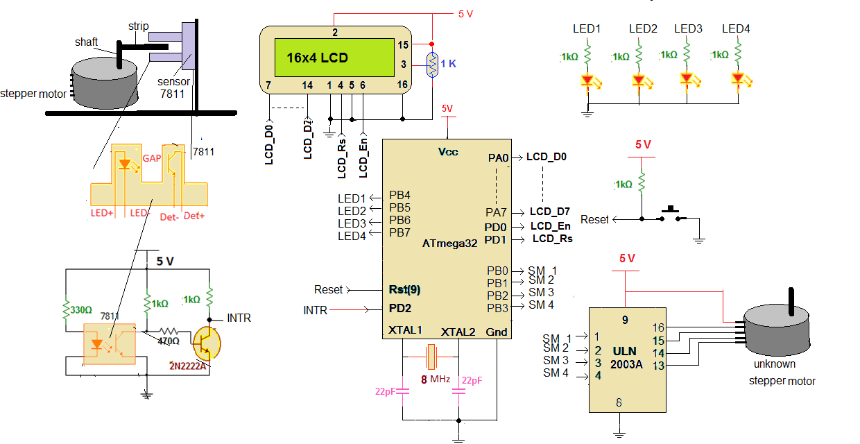
CIRCUIT DESCRIPTION
As shown in above figure, the circuit is build using micro controller ATMega32, motor driver chip ULN2003A, opto interrupt sensor MOC7811 and 16×4 alphanumeric LCD.
• LCD data pins D0 – D7 are connected to ATMega32 port PORTA and control pins Rs and En are connected to PORTD pins PD1 and PD0 respectively. RW pin of LCD is connected to ground to enable LCD write.
• One 1 KΩ pot is connected to LCD pin 3 to vary its contras
• Four LEDs are connected to PORTB pins PB4 – PB7 in common cathode configuration with current limiting resistors of 1 KΩ as shown
• Lower PORTB pins PB0 – PB3 pins drives stepper motor through current driver chip ULN2003A. These pins are connected to inputs of ULN chip and outputs of ULN chip are connected to four coil terminals of unknown stepper motor
• Common terminal of stepper motor is given +Ve supply of 5 V
• Opto interrupt sensor MOC7811 is fixed in such a way that the strip attached to motor shaft passes through the gap of the sensor when the motor rotates.
• The internal IR LED of the sensor is forward biased through the current limiting resistor of 330Ω so it is always ON. Internal photo transistor is connected to 5V supply through 1 KΩ pull up resistor
• The sensor output is inverted and amplified by one more NPN transistor of 2n2222A type. The collector output of this transistor is connected to external interrupt input pin INTR (PORTD pin PD2) of ATmega32
• One 8 MHz crystal is connected to crystal input pins (XTAL1 and XTAL2) to provide internal clock to micro controller
• Reset input pin is pulled high using 1KΩ pull-up resistor and one push button is connected to provide manual reset to micro controller
Here is the snap of circuit and another arrangement.

Fig. 3: Image showing working of Automatic Stepper Motor Step Angle Identifier
CIRCUIT OPERATION
• First, the stepper motor is placed in such a way that the paper strip attached to its shaft is very much closer to a gap of MOC7811 sensor and when motor completes one revolution the strip passes through this gap.
• Then the stepper motor coil terminals are connected to motor driver chip ULN2003A chip outputs in proper sequence and a common terminal of motor is connected to the +Ve supply.
• Now the supply is given to circuit. Initially, the message is displayed on LCD screen as “stepper motor step angle identifier”
• Then the micro controller starts applying pulses to motor and motor starts rotating. The message is displayed on LCD as “rotating the motor and calculating step angle…..” Also, all 4 LEDs blink to indicate pulses applied to the motor.
• The micro controller keep counting number of applied pulses
• When motor completes one revolution, the strip passes through sensor gap and it generates an interrupt
• Micro controller stops applying further pulses to motor, gets the final pulse count and calculates step angle from
Step angle = 360 / pulse count
• Finally, it displays both parameters (1) pulse count (number of pulses applied for 1 revolution) and (2) step angle of motor on LCD
Thus given project/circuit can be used to find step angle of any unknown stepper motor and it gives very accurate result even for those motors that have step angle less than 1o.
Project Source Code
###
#include <avr/io.h> #include <avr/interrupt.h> #include <util/delay.h> #include <string.h> unsigned int pulse_counter=0,stop_motor_flag=0; float step_angle; void lcd_senddata(unsigned char data) { _delay_ms(2); PORTD=(1<<PD0); PORTA=data; PORTD=(1<<PD0)|(1<<PD1); PORTD=(1<<PD0)|(0<<PD1); } void lcd_sendcmd(unsigned char cmd) { _delay_ms(2); PORTD=(0<<PD0); PORTA =cmd; PORTD=(1<<PD1); PORTD=(0<<PD1); } void lcd_printstr(char *s) { unsigned int l,i; l = strlen(s); // get the length of string for(i=0;i<l;i++) { lcd_senddata(*s);// write every char one by one s++; } } void display_pulse_count(unsigned int value) { unsigned char ascii_value[3]; unsigned int tmp,t; if(value>100) { tmp = value%10; ascii_value[2] = tmp+0x30; value = value/10; tmp = value%10; ascii_value[1] = tmp+0x30; value = value/10; ascii_value[0] = value+0x30; } else { tmp = value%10; ascii_value[2] = tmp+0x30; value = value/10; ascii_value[1] = value+0x30; ascii_value[0] = 0x20; } lcd_sendcmd(0x01); lcd_printstr("num of pulses"); lcd_sendcmd(0xC0); lcd_printstr("applied for 360"); lcd_senddata(0xDF); lcd_sendcmd(0x90); lcd_printstr("rotation:"); for(t=0;t<3;t++) lcd_senddata(ascii_value[t]); } void display_step_angle(float t) { unsigned int tmp,tmp1,tmp2,x; unsigned char ASCII[3]; if(t<1.0) { tmp = t*100; tmp1 = tmp % 10; ASCII[2] = tmp1 + 48; tmp2 = tmp/10; ASCII[1] = tmp2 + 48; ASCII[0] = '.'; } else if(t<10.0) { tmp = t*10; tmp1 = tmp % 10; ASCII[2] = tmp1 + 48; tmp2 = tmp/10; ASCII[0] = tmp2 + 48; ASCII[1] = '.'; } else if((t>=10.0) && (t<100.0)) { tmp = t*1; tmp1 = tmp % 10; ASCII[2] = tmp1 + 48; tmp2 = tmp/10; ASCII[1] = tmp2 + 48; ASCII[0] = ' '; } lcd_sendcmd(0xD0); lcd_printstr("step angle:"); for(x=0;x<3;x++) lcd_senddata(ASCII[x]); lcd_senddata(0xDF); } void lcd_init() { lcd_sendcmd(0x3E); lcd_sendcmd(0x0E); lcd_sendcmd(0x01); lcd_sendcmd(0x81); lcd_printstr("Stepper Motor"); lcd_sendcmd(0xC3); lcd_printstr("step angle"); lcd_sendcmd(0x93); lcd_printstr("identifier"); } void main() { DDRA = 0xFF; DDRB = 0xFF; DDRD = 0x03; PORTA = 0x00; PORTB = 0x00; PORTD = 0x04; MCUCR = (1<<ISC01) | (0<<ISC00); GICR=(1<<INT0); lcd_init(); _delay_ms(2000); lcd_sendcmd(0x01); lcd_printstr("Rotating Motor"); lcd_sendcmd(0xC0); lcd_printstr("and calculating"); lcd_sendcmd(0x90); lcd_printstr("step angle....."); sei(); while(stop_motor_flag==0) { pulse_counter++; PORTB = 0x11; _delay_ms(20); pulse_counter++; PORTB = 0x22; _delay_ms(20); pulse_counter++; PORTB = 0x44; _delay_ms(20); pulse_counter++; PORTB = 0x88; _delay_ms(20); } step_angle = 360.0/pulse_counter; display_pulse_count(pulse_counter); display_step_angle(step_angle); } ISR(INT0_vect) { stop_motor_flag=1; MCUCR = (0<<ISC01) | (0<<ISC00); GICR=(0<<INT0); _delay_ms(200); }###
Circuit Diagrams
Project Video
Filed Under: Electronic Projects
Filed Under: Electronic Projects

Questions related to this article?
👉Ask and discuss on EDAboard.com and Electro-Tech-Online.com forums.
Tell Us What You Think!!
You must be logged in to post a comment.