In this project, we’ll design an omnidirectional, moving pick-and-place robot. First, let’s cover how the robot is built. The robot’s build As shown in Figure 1, the robot consists of two sections: An omnidirectional moving platform A robotic arm The omnidirectional platform The robot is built using one circular wooden plate, three dc gear motors,…
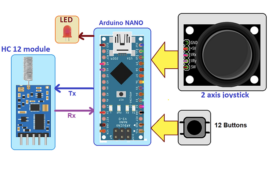
How to turn Arduino into 16-bit IO port
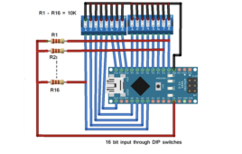
In this project, we’ll design a 16-bit IO port (input-output port) library for Arduino. It’s possible to send direct 16-bit data to any Arduino board using this library. It connects any of Arduino’s 16 pins, so they work as a 16-bit IO port. First, you must select 16 pins from Arduino to combine as the…
How to design an Arduino library for an 8-bit IO port
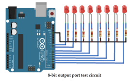
In this project, we’ll create an 8-bit IO port Arduino library that reads and writes all eight bits in a single command by combining Arduino’s pins. This means sending and receiving the 8-bit data from a single pin will be possible. Arduino provides digital output using the digitalWrite() function and receives digital input via the…
ESP32 voice-operated home automation with ThingSpeak MQTT, IFTTT and Google Assistant
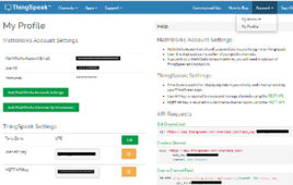
This article explains how to build a voice-based Home Automation to control Home Appliances. Google Assistant is used to input voice commands or text commands. The main intention of this project is to introduce various IoT tools and integrate them to build a real-time project. As home automation is a friendly project, it is chosen…
How to design a multi-use level indicator using Arduino

In this mini do-it-yourself (DIY) electronic project, we’ll design a multi-use level indicator that can measure multiple physical parameters like temperature, water, voltage, humidity, distance, and more. It consists of a bar-graph LED display that presents the measurements. Four main types of sensors are used to measure the different physical parameters, including the following LM35…
Forest fire detection system using IoT sensor network
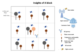
In this article, we will be detecting a forest fire using an IoT sensor network and making a portable device with battery operation. Getting information about a fire hazard in a forest in time can prevent the forest fire from spreading. The sensor network can give the particular location of the fire as we already…
How to design a rechargeable LED table lamp
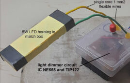
In this mini do-it-yourself (DIY) project, we’ll design an LED table lamp that’s battery-operated and rechargeable. It will also feature light dimming so you can adjust the lamp. There are two basic types of lamps available on the market. A typical one with a 3 to 5-W LED bulb that works on a 230 V…
How to design a lab power supply at home
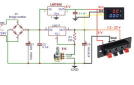
The voltage requirements for different circuits vary much like microcontroller-based circuits require 5 V, motor controller or relay driver circuit requires 12 V, and other digital circuits require 3.3 V. If a circuit fails to receive its rated voltage and current, it will not work properly. So, it often makes sense to use a variable…
VHDL tutorial 13: Design 3×8 decoder and 8×3 encoder using VHDL
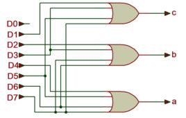
In the previous tutorial VHDL tutorial, we designed an 8-bit parity generator and 8-bit parity checker circuits using VHDL. (If you are not following this VHDL tutorial series one by one, you are requested to go through all previous tutorials of these series before going ahead in this tutorial) In this tutorial, We shall write…
VHDL Tutorial 14: Design 1×8 demultiplexer and 8×1 multiplexer using VHDL

In the previous tutorial VHDL tutorial, we designed 8×3 encoder and 3×8 decoder circuits using VHDL. (If you are not following this VHDL tutorial series one by one, you are requested to go through all previous tutorials of these series before going ahead in this tutorial) In this tutorial, We shall write a VHDL program…
VHDL Tutorial 15: Design a clocked SR latch (flip-flop) using VHDL

Note: it’s recommended to follow this VHDL tutorial series in order, starting with the first tutorial. In the previous tutorial, VHDL tutorial – 14, we designed two circuits using VHDL: a 1×8 de-multiplexer and a 8×1 multiplexer. In this project, we will, Write a VHDL program to build a clocked SR Latch (flip-flop) circuit Verify the…
VHDL Tutorial 16: Design a D flip-flop using VHDL
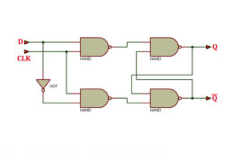
Note: it’s recommended to follow this VHDL tutorial series in order, starting with the first tutorial. In the previous tutorial, we designed a clocked SR latch circuits using VHDL (which is a very high-speed integrated circuit hardware description language). For this project, we will: Write a VHDL program to build a D flip-flop circuit Verify the…
VHDL Tutorial 17: Design a JK flip-flop (with preset and clear) using VHDL

Note: it’s recommended to follow this VHDL tutorial series in order, starting with the first tutorial. In the previous tutorial – VHDL tutorial 16 – we designed a D flip-flop circuit by using VHDL. For this project, we will: Write a VHDL program to build a JK flip-flop circuit Verify the output waveform of the program…
VHDL Tutorial 18: Design a T flip-flop (with enable and an active high reset input) using VHDL

Note: it’s recommended to follow this VHDL tutorial series in order, starting with the first tutorial. In the previous tutorial, VHDL tutorial – 17, we designed a JK flip-flop circuit by using VHDL. For this project, we will: Write a VHDL program to build the T flip-flop circuit Verify the output waveform of the program (the…
How to design a smartphone-operated door lock
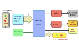
In this project, we’ll design a unique door lock that can be operated without a keycard, input password, or biometric ID. A smartphone is the key to locking and unlocking the door via Bluetooth. This door uses a solenoid lock, which relies on a latch for electrical locking and unlocking. It also has LEDs to…
DC motor controller using rotary encoder
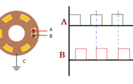
Controlling a DC motor means: Start and stop the motor Change the running direction of the motor as forward (CW) or reverse (CCW) Vary motor speed (RPM) All different types of DC motor controllers control the speed and direction of the motor. They use different types of input devices like Two push-buttons (or maybe a…
How to build 100W 2.1-channel home theater system
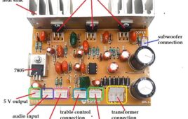
In this mini DIY project, we will build a 2.1-channel home theater system of 100 W with a deep base and crystal-clear sound output at a very low cost of 1200/- to 1500/- Rupees only. Big speaker systems like 2.1 / 4.1 / 5.1-channel, home theater systems with Bluetooth connectivity and excellent quality sound (crystal…
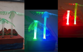
How to make a decorative coconut tree using a digital RGB LED strip
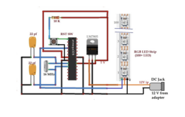
In this project, we’ll demonstrate how to make a colorful, king-sized coconut tree (5 feet) decorative showpiece using a digital RGB LED strip. The RGB LED strip is cut and arranged to form the shape of a coconut tree. The ATMega328 microcontroller is used to control the LED strip, generating several flashing, fading, and blinking…
RGB LED decorative, tabletop coconut tree
In this mini-DIY project, we will make a color-flashing coconut tree. It has two 3W RGB LEDs using, which generate multicolor flashing effects. Also, a tiny 8-pin microcontroller ATtiny85 generates eye-catching colorful LED-chasing effects. It is battery-operated, and the battery is rechargeable so it does not require a power connection through wires. It can be…
Basic Electronics 01 – Beginners guide to setting up an electronics lab

Electronics is ubiquitous in the modern era. Learning electronics is a never-ending fun ride. Not just a career, it can also be an exciting hobby to take up. Most of the electronics enthusiasts, however, do not know how to get started. They usually have a random beginning that takes a lot of time and effort…