There are many devices for visually impaired people. This project is also an attempt to develop an aid for visually impaired persons. This project is a smart stick which is capable of detecting any obstacle, detect water and corners and even allow the user to find the stick if anyhow missed by the user by pressing a remote switch. The device is designed with an intention to sort out common issues faced by the blind people while using traditional sticks. With the electronics embedded within the stick, it became a smart stick with the functionalities mentioned above.
The smart stick is built on Arduino Pro Mini. This Arduino board is small enough to install on a regular stick and has buzzer, LDR sensor, Ultrasonic sensor and a water detector sensor interfaced to it. The stick also has an RF receiver which connects with an RF transmitter that acts as a remote for finding the stick on missing. The remote built on RF transmitter has a switch pressing which, the buzzer installed on the stick is triggered and by the sound of the buzzer a blind person can find the stick. The ultrasonic sensor detects obstacles and LDR sensor allows determining the lighted and dark places. A water indicator is also installed at the base of the stick which invokes an alarm if the person is going step into any wet place.
The Arduino sketch manages to detect an obstacle, sense light, and water and invoke alarm on the press of the remote switch. The sketch is written on Arduino IDE and burnt to the controller board using the same. For demonstration, the circuit is built on a breadboard and it can be easily installed on any regular blind stick.
Components Required –
– Arduino Pro Mini
– HR-SR04 Ultrasonic Sensor
– Buzzer
– LDR Sensor
– BC-548 transistor
– 5K ohm pot
– metal strips
– Connecting wires
– Breadboard
– 10K ohm resistors – 3
– HT12D decoder IC
– RF receiver
– HT12E encoder IC
– RF Transmitter
– tactile switch
Circuit Connections –

Fig. 1: Prototype of Arduino Based Smart Blind Stick
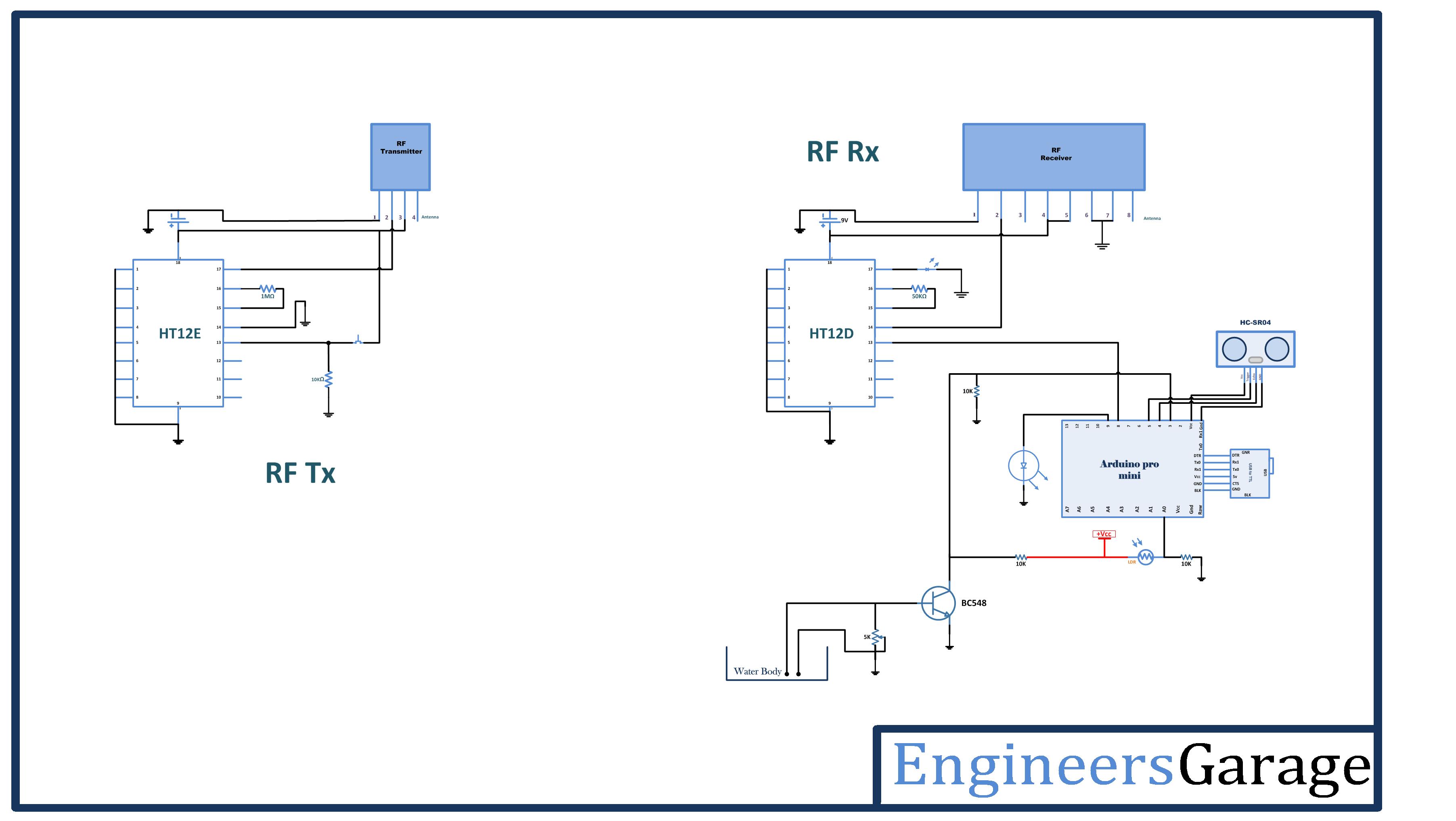
There are two circuits in the project – remote switch and the smart stick. The remote switch is simply an RF transmitter circuit with a switch connected to the D3 pin of the encoder IC. The remote switch has the following circuit connections –
RF Transmitter – The RF transmitter is used to transmit the missing alert to the receiver circuit on the smart stick. The RF transmitter module is a small PCB sub-assembly. The pin configuration of transmitter module is as follow-

Fig. 2: Table listing pin configuration of RF Transmitter
The serialized data from the encoder is received at pin 2 of the module and passed on to the antenna from pin 4 of the module.
HT12E IC – The HT12E IC converts the parallel data into serial data for passing it to the RF transmitter. HT12E encoder IC belongs to the 212 series of encoders. It is paired with 212 series of decoders having the same number of addresses and data format. HT12E is capable of encoding 12 bits, out of them 8 are address bits and 4 are data bits. Thus the encoded signal is a serialized 12-bit parallel data comprising of 4-bit data to be transferred appended with the address byte. In the circuit, an only D3 bit of the RF data is utilized. A tactile switch is connected to the D3 bit of the encoder. The switch is connected between data pin and the VCC. The D3 data pin by default receives a LOW logic. The address byte of the encoder IC is set to 0x00 by hard-wiring all the address bits to the ground.
The smart stick is built on Arduino Pro Mini and has RF receiver circuit, ultrasonic sensor, LDR sensor, Buzzer and water level indicator circuit connected to the Arduino board. The circuit connections of the smart stick are as follow –
RF Receiver – The RF receiver detects the missing alert at a D3 bit of the RF data. The receiver detects the radio signal carrying the alert information. The RF receiver module has 8 pins and has following pin configuration –
Fig. 3: Table listing pin configuration of RF Receiver
HT12D Decoder – The signal detected by the RF receiver is passed to the HT12D decoder. It converts the serial data back to the parallel data after separating data and addresses. HT12D belongs to the 212 series of decoders and can be paired with 212 series of encoders having the same number of addresses and data format. HT12D is capable of decoding 12 bits, out of them 8 are address bits and 4 are data bits. The 4-bit data is of latch type and when passed to the output data pins it remains unchanged until the new data is received. The D3 bit of the decoder IC is connected to the pin 8 of the Arduino board. The address byte of the decoder is set as same as of the encoder IC on transmitter circuit which is 0x00 by connecting all the address pins to the ground.
HC-SR04 Ultrasonic Sensor – The ultrasonic sensor is connected to pins 5 and 4 of the Arduino board. The ultrasonic sensor has four pins – Ground (Pin 1), Echo (Pin 2), Trigger (Pin 3) and Trigger. The VCC and ground pins are connected to common VCC and Ground respectively. The Echo pin is connected to pin 4 of the Arduino board while Trigger pin is connected to pin 5 of Arduino board. The ultrasonic sensor works on the principle of echo of sound waves. When a HIGH pulse of 10 u sec is passed to the trigger pin of the sensor, it transmits eight 40 KHz waves of HIGH Sonic Pulse shots back to back. A High pulse signal is out from the echo pin as the ultrasonic wave is transmitted. This wave when collides with an obstacle, it is reflected back and detected by the sensor. On detecting the wave again, the High pulse signal from the echo pin of the sensor is terminated. The signal received from the echo pin is analog in nature. The distance from the obstacle can be measured by measuring the high time of the echo pin. This is the time between the transmission and reflection back of the sonic wave. The distance is given by the formulae –
Test distance = (high level time × velocity of sound (340M/S)) / 2
The time multiplied by velocity is divided by 2 as the time taken is for the sonic wave to reach obstacle and return back. Therefore the distance measurement in cm can be given by the formulae –
Test distance = (high level time × velocity of sound (340M/S)) / 2
= (high level time(microsecond) × velocity of sound (340M/S)) / 2
= high level time x 340/2000000 m
= high level time x 34000/2000000 cm
= high level time x 34/2000 cm
The ultrasonic sensor outputs the high pulse from pin 2 which is detected at the pin 4 of the Arduino Board. The program code measures the pulse duration and digitizes it to a distance value using the formulae stated above.
LDR Sensor – The LDR sensor is used to identify the dark and lighted places. The LDR sensor is connected to the A0 pin of Arduino board. The sensor is connected in a voltage divider circuit. The LDR provides an analog voltage which is converted to digital reading by the inbuilt ADC of the controller.
Water Indicator Circuit – Water is a good conductor of electricity. Using the same principle, a water indicator circuit is built. There are two metal strips used of which one is attached to the base of the stick and another 1 mm above the base of the stick. The metal strip above the base of the stick is connected to the base of a BC-548 switching transistor and another metal strip attached at the base of the stick is connected to a potentiometer connecting to the ground. The potentiometer helps in calibrating the water sensor. The collector pin of the transistor is connected to the pin 3 of the Arduino board and the VCC. The emitter of the transistor is grounded. When the water is detected, the base of the transistor is triggered and the VCC at the pin 3 of Arduino is short-circuited to the ground. Otherwise, the pin keeps receiving a HIGH logic.
Buzzer – The buzzer is directly interfaced at the pin 9 of the Arduino. The buzzer is activated as any obstacle is detected by the ultrasonic sensor, the wet place is detected by the water sensor, dark spots are detected by LDR sensor or the missing alert is passed by the RF circuit.
Power Supply – Both the circuits need a 5V regulated DC for their operation. An 18V battery can be used as the primary source of power. The supply from the battery can be regulated to 5V using 7805 voltage regulator IC. The pin 1 of the voltage regulator IC should be connected to the anode of the battery and pin 2 of it should be connected to the ground. The voltage output must be drawn from pin 3 of the 7805 IC.
How the circuit works –

Fig. 4: Image of Arduino Based Smart Blind Stick
The Arduino board at the smart stick manages the functionality of the entire device. The board manages the following four functions implemented in the project –
Obstacle detection – The obstacle detection is done by the Ultrasonic sensor. For reading data from the ultrasonic sensor, first a pulse has to be sent to the trigger pin of the sensor and then the analog voltage is read from the echo pin. The analog voltage is converted to digital reading using inbuilt ADC channel and converted to distance measurement using the formulae stated above. If the distance measured by the ultrasonic sensor is detected less than 10 cm, a HIGH pulse is passed at the pin connected to the buzzer. The pulse lasts for an infinite time until the user gets away from the obstacle.
Light detection – The light detection is done by the LDR sensor and is used to detect the dark places. The sensor connected to a voltage divider circuit output an analog voltage at the interfaced controller pin. The analog voltage is read and digitized using inbuilt ADC channel. The analogRead() function is used to read analog voltage at the controller pin.
Water detection – The water indicator circuit operates by triggering the base of the switching transistor. When the stick steps on water, the metal strips are short-circuited by the water triggering a pulse at the base of the transistor. As the transistor is triggered, the VCC at the collector pin is shorted to the ground through emitter pin and a LOW logic is passed at the pin 3 of the Arduino.
Stick location detection – If any how the user loses the stick, he can press the remote switch which set the D3 bit of the RF encoder to HIGH. The same logic is relayed at the D3 bit of the RF decoder and passed to pin 8 of the Arduino. On receiving a HIGH logic at the pin, the Arduino send a pulse at the buzzer which lasts for a variable duration depending upon the distance of the remote from the stick.
Programming Guide –
In the Arduino sketch, first, the constants and variables are declared indicating circuit connections of the ultrasonic sensor, LDR, water sensor, buzzer and the RF receiver. A variable is declared to store buzzer duration corresponding to missing alarm.
#define trigPin 5
#define echoPin 4
int ldr = A0;
int Watersensor = 3;
int Buzzer = 9;
int RF = 8;
int brightness = 0;
int fadeAmount = 5;
The setup() function is called which runs for once. In the function, the sensor and RF decoder connected pins are set to digital input and pin connecting to buzzer and trigger pin of ultrasonic sensor are set to digital output using pinMode() function.
void setup()
{
Serial.begin(9600); // set your baud rate
pinMode(trigPin, OUTPUT);
pinMode(echoPin, INPUT);
pinMode(Watersensor,INPUT);
pinMode(Buzzer,OUTPUT);
pinMode(RF,INPUT);
}
The loop() function iterates infinitely. In the function, the digital data from the water sensor and RF decoder are read using digitalRead() function while analog voltage from LDR sensor and ultrasonic sensor is read using analogRead() function. The sensor values are compared with limiting values and buzzer is activated for the variable duration for each sensor. For missing alarm functionality, the duration of buzzer sound varies according to the distance of the stick from the handheld remote.
The ultrasonic() function is used to sense analog voltage from the ultrasonic sensor and calculate distance as specified by the sensor’s datasheet. First, a pulse is generated at trigger pin and pulse duration in the form of analog voltage is read using pulseIn() method and stored to variable duration. The pulse duration is converted to distance measurement using standard conversion formulae. The value of the distance is returned by the function.
You would find the complete code for Smart Stick for Blinds in the source code tab.
Project Source Code
####define trigPin 5 #define echoPin 4 int ldr = A0; int Watersensor = 3; int Buzzer = 9; int RF = 8; int brightness = 0; int fadeAmount = 5; void setup() { Serial.begin(9600); // set your baud rate pinMode(trigPin, OUTPUT); pinMode(echoPin, INPUT); pinMode(Watersensor,INPUT); pinMode(Buzzer,OUTPUT); pinMode(RF,INPUT); } void loop() { Serial.print(ultrasonic()); int WS=digitalRead(Watersensor); int missingalarm=digitalRead(RF); if(LDR() < 200) { digitalWrite(Buzzer,HIGH); delay(300); digitalWrite(Buzzer,LOW); delay(100); } else if(WS == LOW) { digitalWrite(Buzzer,HIGH); delay(100); digitalWrite(Buzzer,LOW); delay(30); } else if(missingalarm == HIGH) { analogWrite(Buzzer, brightness); brightness = brightness + fadeAmount; if (brightness == 0 || brightness == 255) { fadeAmount = -fadeAmount ; } delay(30); } else if(ultrasonic() < 10) { digitalWrite(Buzzer,HIGH); //delay(1000); } else if (missingalarm == LOW || ultrasonic() > 10 || WS == LOW || LDR() > 200) { digitalWrite(Buzzer,LOW); } } int LDR() { int LDR=analogRead(ldr); return LDR; } int ultrasonic() { long duration, distance; digitalWrite(trigPin, LOW); delayMicroseconds(2); digitalWrite(trigPin, HIGH); delayMicroseconds(10); digitalWrite(trigPin, LOW); duration = pulseIn(echoPin, HIGH); distance = (duration/2) / 29.1; Serial.println(distance); delay(30); return distance; }###
Circuit Diagrams
Project Video
Filed Under: Electronic Projects
Filed Under: Electronic Projects

Questions related to this article?
👉Ask and discuss on Electro-Tech-Online.com and EDAboard.com forums.
Tell Us What You Think!!
You must be logged in to post a comment.