In the previous tutorial, we learned how to interface a buzzer with Arduino. A buzzer is an audio signaling output device. Embedded systems are built by interfacing several input and output devices with a controller or computer.
In this tutorial, we’ll interface an input device — specifically, a TTP229 capacitive touch keypad — with Arduino. The TTP229 is a popular, 4×4 keypad that supports 8/16 key inputs with single and multi-key options. Interestingly, it can be interfaced with a microcontroller or Arduino by using only two pins.
Keypads are the most common input devices used in embedded systems. In this case, an “input device” refers to a component used to input data or commands by the user.
There was a time when matrix keypads, designed by multiplexing push buttons, were typically used as keypads. However, these types of keypads required many pins to interface with a controller/computer and the only way the key input could be detected was polling by the microcontroller/microprocessor.
Matrix keypads
For a long time, matrix keypads have been a popular human interface component for embedded systems. These keypads are designed by multiplexing push buttons into rows and columns, which form a matrix of push buttons. Each push-button is connected to only one row and only one column.
Membrane keypads are now available and come in sizes 4×4, 4×3, 4×2, 4×1, and others. A 4×4 matrix keypad has four rows and four columns. A 4×3 matrix keypad has four rows and three columns, and a 4×1 matrix keypad has four rows and one column.
This is a circuit diagram of a 4×4 membrane keypad:
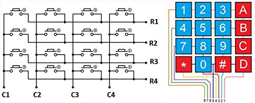
Each push button in the matrix keypad is connected to only one row and one column.
How matrix keypads work
To detect a matrix keypad’s input, the rows and columns must be interfaced with the microcontroller. This is done by interfacing all of the row and column terminals with the microcontroller pins via current-limiting resistors, which are connected in a series — between each terminal and the respective controller pin.
The row pins are set as digital output and the column pins are set as digital input or vice versa. The keypad can operate active-HIGH or active-LOW.
Now, let’s suppose the row pins are set to the digital output and the column pins are set as a digital input. The controller is, then, programmed such that the keypad operates as active-HIGH. Each row is set to HIGH, one after the other, and the digital input of all of the columns is polled.
As each button is connected to only one row and one column, if a button is pressed, the logical signal (which is HIGH in this example) will be detected, but for only one of the columns. As such, the key that’s pressed can be identified. The controller can also be programmed to interpret the key input as data or a command.
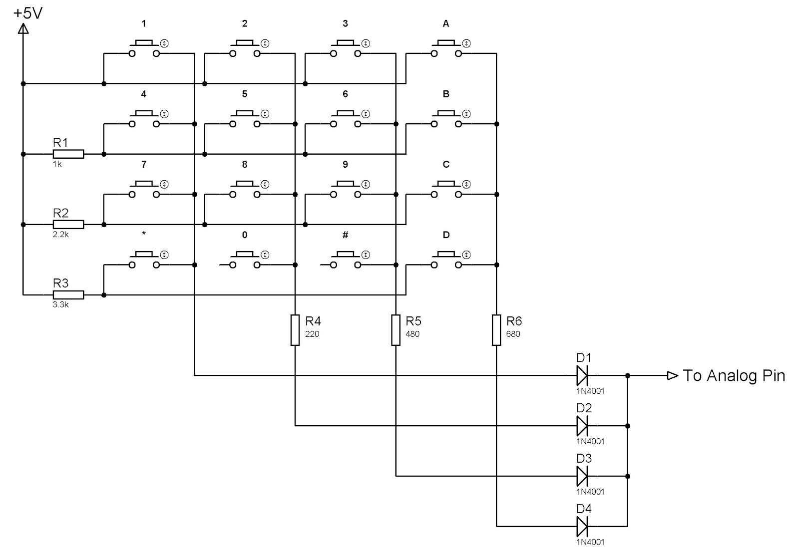
The analog input is another way that the input from a matrix keypad can be detected. In this method, the rows are connected to the VDD (5V DC) via different values of the resistances. And, the columns are connected to the analog input pin of the microcontroller via the other values of the resistances.
Each button connects only one row and one column. When pressing each button, the voltage from the VDD drops across different combinations of resistances. As a result, there’s a different voltage detected at the analog input pin. This method requires manual inspection of the voltage levels when each button is pressed on the keypad and according to the design of the microcontroller program.
The drawback
Although the matrix keypads have been a popular choice for microcontroller projects, they do have some cons. For one, these keypads use mechanical buttons but there’s been an effort in embedded systems to replace mechanical switches and buttons.
Secondly, several digital I/O pins are necessary to properly interface with a matrix keypad. When using the analog input method (which uses one wire for interfacing), the controller must have an analog input pin and voltage levels that correspond to each button — and it must be verified manually.
Unfortunately, this can lead to input errors when the embedded device is used in wide operating conditions. The resistances can change, vary, or experience damage depending on the environmental conditions, which can lead to errors. This is because the controller is programmed to sense a limited range of voltages respective to each button.
Capacitive touch buttons
In electronics, resistance or capacitance is typically employed for touch sensing. Capacitive touch sensing is preferred and will use mutual or self-capacitance. The touch displays use mutual-capacitance configurations. The touch buttons, sliders, and wheels use self-capacitance configurations.
In mutual-capacitance configuration (used by touch screens and touch displays), the capacitance between a receiving and emitting electrode of the sensor changes with touch. In self-capacitance configuration (used by touch buttons and sliders), the capacitance of the sensor changes with respect to the printed circuit board (PCB) ground and touch.
For a touch button, its self-capacitance increases when a human finger touches it. This happens because of the dielectric property of human flesh and the conductive property of the human body. The human body is made up of about 70% water. In comparison, the dielectric constant of water is 80% while that of the air is just 1.0006%.
As a result, the capacitive touch button has a conducting surface, which is sandwiched between the two surfaces connected to the PCB ground.

A simple touch of the finger can increase the capacitance of the conducting surface in relation to the PCB ground. This occurs because of the high-dielectric constant from the finger. Additionally, due to the conductive nature of the human body, the finger acts as a virtual ground forming a parallel capacitance — which further increases the self-capacitance of the touch sensor.
Thanks to the dielectric and conductive properties of the human finger, the self-capacitance of a capacitive touch button are increased when touched. This change in capacitance is in picofarads and requires advanced integrated circuitry for proper sensing.
The TTP229 capacitive touch module
The TTP229 capacitive touch module is a 4×4 capacitive touch keypad. Similar touch modules include the TTP226 (4×2 capacitive touch keypad) and the TTP224 (a 4×1 capacitive touch keypad).
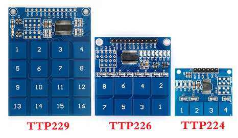
The TTP229 touch module is based on the TTP229 16/8 keys touchpad detector IC. By default, the module comes configured as 8-keys that are enabled as a single-key configuration.

The TTP229 capacitive touch keypad IC
The TTP229 has capacitive sensing that’s specifically designed for touchpad controls. It has a built-in regulator for the touch sensors that enable stable sensing in diverse conditions.
The IC can handle 8 or 16 touch buttons and supports single and multi-key options. For the single key, the same value is output even if the touch button is pressed several times or rapidly. For the multi-key, different values are output if the touch button is pressed several times rapidly.
Additionally, it has 8 separate outputs for 8 direct input keys and supports an I2C compatible bus for the eight 8 and 16 direct input keys. Even for the 8 separate outputs, the output driving types (CMOS/Open-Drain/Open-Collector) can be selected with options (active HIGH/LOW).
The IC requires an operating voltage of 2.4V~5.5V. It has an operating current of only 20 uA without a load and an output port sink current of only 8 mA (at 3V supply). Therefore, it can be directly interfaced with the digital I/O pins of any microcontroller/processor. Arduino can source and sink up to 40 mA current.
After the power is turned on, the IC requires a stable time of only 0.5 seconds and has a maximum key-on time of 80 seconds. The sensitivity can be adjusted by a capacitance of 1~50pF outside.
The TTP229 also supports auto-recalibration, which takes a maximum of four seconds. There are two sampling rates available: 8 Hz for slow sampling and 64 Hz for fast sampling.
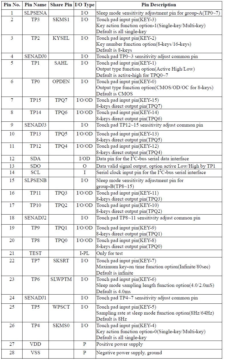
The TTP229 IC has this pin diagram:
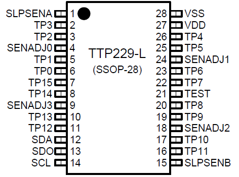
The TTP229 has this pin configuration:
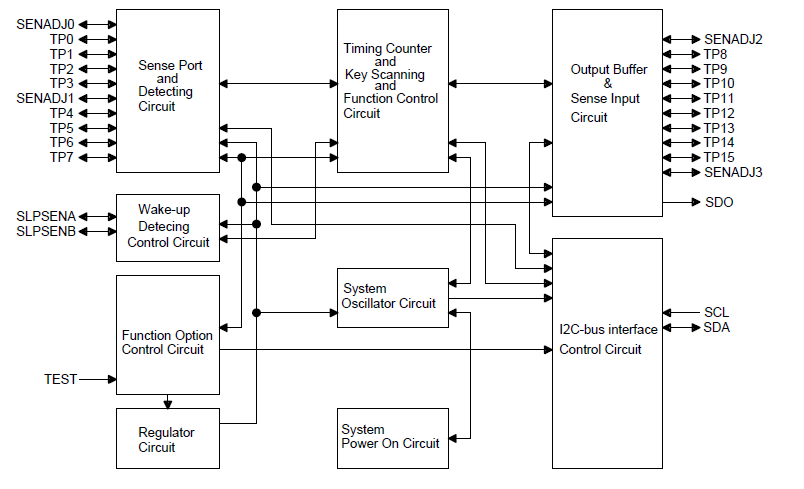
The TTP229 has this block diagram:
On the touch module, the touch buttons are interfaced with the TTP229 IC as shown in this circuit diagram:
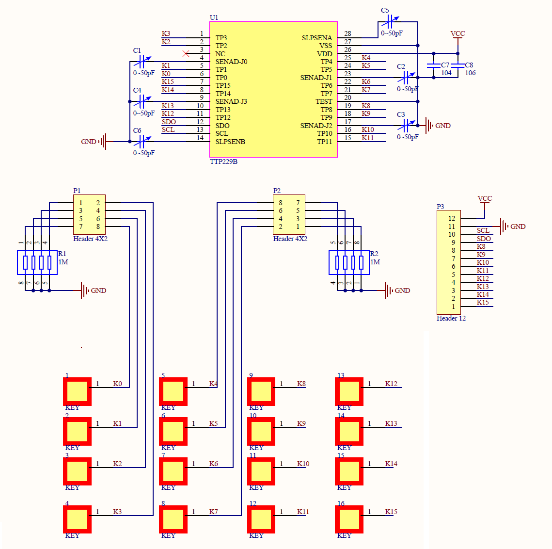
As is evident from this circuit diagram, the TTP229 module has three headers. The headers P1 and P2 are connected to the option pins (TP0~TP7) and header 3 is connected to the output pins (TP8~TP15).
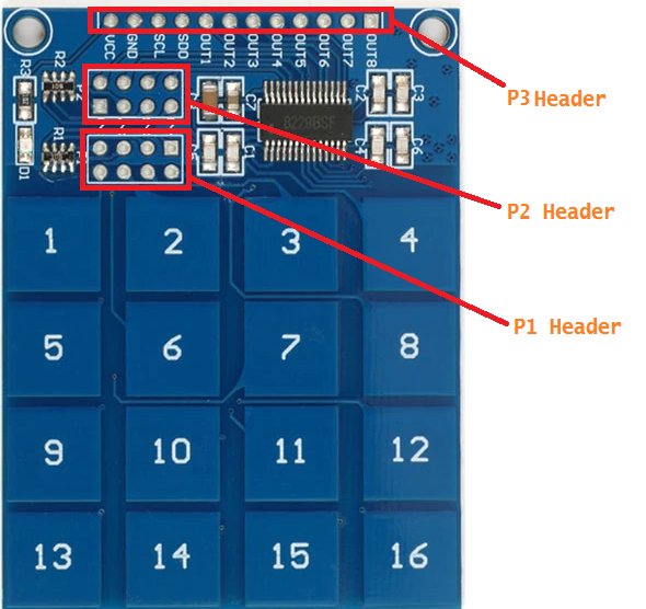
These headers are located in the module as shown here:
TTP229 capacitive touch keypad options
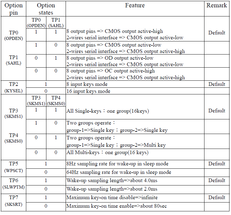
The TTP229 capacitive touch keypad IC offers several configurable options. These options can be enabled by connecting or not connecting the option pins TP0~TP7 to VSS (the system ground/PCB ground).
Various keypad configuration options are available on the TTP229 IC and their settings are summarized here:
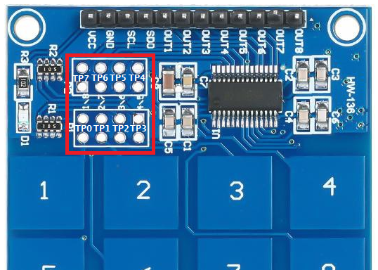
On the touchpad module, the option pins are available on the P1 and P2 headers. The option pins TP0~TP7 are available on the P1 and P2 header as shown here:
For example, by default, only the 8 input keys (buttons 1~8) are enabled on the module. To enable the 16 input keys, the TP2 option must first be connected to the VSS via a HIGH-value resistor. This can be done by shorting the TP2 option pin on the P1 header using a jumper as shown here:

Solder bug strip the connectors to the P1 and P2 headers and short the required option pins by using the jumper caps. Then, different keypad options can be enabled or set by shorting or leaving the option pins unconnected to the VSS via the HIGH-value resistors.
The resistors are on-board in the module. The user need only short the header pins or leave them unconnected.
Interfacing TTP229 capacitive touch keypad with Arduino
The TTP229 capacitive touch keypad module can be interfaced with any microcontroller or to Arduino using its P3 header. The module, by default, is configured to 8 input keys mode. These are all of the keys necessary to operate in a single-key configuration.
These 8 input keys are available through the touch buttons 1 through 8 on the keypad. By default, the 8 input keys have 8 separate direct outputs on the P3 header as shown here:
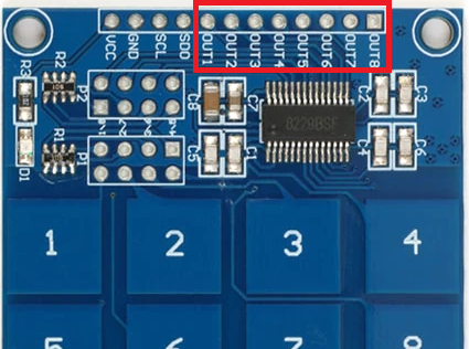
In the 8-key mode, the input keys (touch buttons 1~8) can be directly accessed through the P3 header. The output pins from the P3 header can be directly interfaced with Arduino’s digital I/O pins (or any microcontroller).
As the direct outputs are active HIGH by default, the Arduino must be programmed to poll for the logical HIGH from these P3 header output pins.
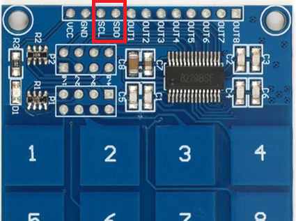
Another way to get the input from this touch keypad is by using its I2C compatible bus. The I2C compatible bus on the TTP229 keypad is available for both the 8 and 16-key modes. This two-wire bus is available on the P3 header as shown here:
Note:
- By default, the keypad is in the 8-key mode.
- The SDO pin on the P3 header outputs the 8-bit serial data, indicating the status of the touch buttons 1~8.
- The 16-key mode can be enabled by shorting the TP2 option pin to the VSS, using a jumper cap in the P1 header.
- When the 16-key mode is enabled, the SDO pin on the P3 header outputs the 16-bit serial data, indicating the status of touch buttons 1~16.
- The bits B0~B15 of the serial data indicates the status of the ouch buttons 1~16, respectively.
- By default, the output of the 2-wire bus is the CMOS output active-LOW.
- If the bit is 0, it indicates that the respective touch button was pressed. If the bit is 1, it indicates that the respective touch button was not pressed.
Reading touch keys from TTP229 module
If the touch keypad is configured to the 8-key mode, the status of the touch buttons can be detected through direct output pins or the 2-wire interface bus. By default, the direct output pins are active HIGH.
Therefore, if the respective pin outputs a logical HIGH, this indicates that it’s been pressed by the user.
The logical signal from the direct output pins can be detected at Arduino’s digital I/O pins. However, this method engages 8 pins on Arduino for reading the status of the 8 touch buttons. The status of the touch buttons can also be detected from the 2-wire interface.
This 2-wire interface is I2C-compatible but is not exactly an I2C bus. For the 8-key mode, the module outputs 8-bit data that can be sampled by applying clock pulses to the SCL pin. The bits can be sampled on the rising edge of the clock pulses. Additionally, the user needs to sample 8 bits by applying 8 clock pulses to SCL pin.
The touch keypad can be configured to a 16-key mode by shorting the TP2 option pin to the VSS. In this mode, the status of the touch buttons 1~16 can be detected only through a two-wire interface. The two-wire bus outputs 16-bit serial data, where each bit of the data can be sampled on the rising edge of the applied clock pulses.
How the serial data bits indicate the status touch buttons depends on the keypad configuration set by the TP0 and TP1 option pins. By default, both pins are connected to the VDD (logical HIGH), which sets the CMOS output active-HIGH for the direct output pins and the CMOS output active-LOW for the 2-wire interface bus.
If TP1 is shorted to the VSS while TP0 is left connected to the VDD, the direct output pins are set to the CMOS output active-LOW and the 2-wire interface is set to the CMOS output active-HIGH.
If TP0 is shorted to the VSS while TP1 is left connected to the VDD, the direct output pins are set to the open-drain, output active-LOW and the 2-wire interface is set to the CMOS output active-LOW.
If both TP0 and TP1 are shorted to the VSS, the direct output pins are set to the open-collector, output active-HIGH and the 2-wire interface is set to the CMOS output active-HIGH.
According to the keypad configuration set by TP0 and TP1 option pins, the direct output pins can be polled or the serial data from the 2-wire interface can be interpreted in the Arduino sketch (or microcontroller firmware).
Recipe: Reading input from TTP229 capacitive touch pad with 16 key input/single key option using Arduino
In this recipe, we’ll interface the TTP229 capacitive touch keypad with Arduino UNO by configuring the keypad to a 16-key mode and a single-key configuration.
We’ll then read the status of the keypad’s touch buttons via the 2-wire interface bus of the keypad. The buttons will be detected on Arduino IDE’s Serial Monitor.
Components required
- Arduino UNO x1
- TTP229 touch keypad x1
- Bug strip x1
- Jumper cap x1
- Jumper wires
- Computer x1
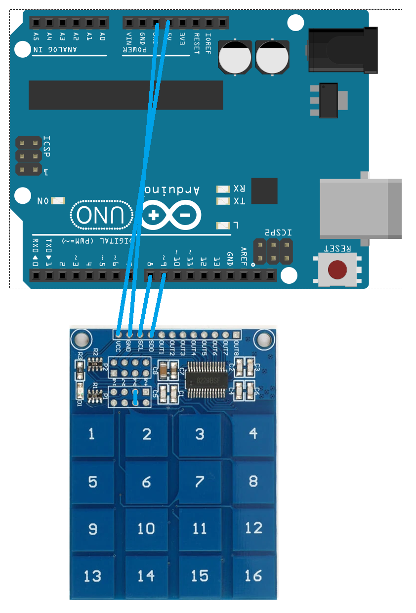
Circuit connections
Configure the TTP229 keypad to a 16-key mode. For this, the TP2 option key needs to be shorted to the VSS. To do so, solder bug strip to the P1 header while shorting the TP2 pins using a jumper cap. The keypad module is supplied 5V DC (VDD) and ground from Arduino UNO.
The pins of the 2-wire interface bus on the keypad can be interfaced to any of Arduino UNO’s digital I/O pins.
In this tutorial, the SCL and SDO pins from the P3 header of the TTP229 keypad are interfaced with Arduino UNO’s pins 8 and 9. Arduino is connected to a computer and the key number of the pressed touch button is observed on Arduino IDE’s Serial Monitor.
The Arduino sketch
#define SCL 8
#define SDO 9
byte Key;
byte Read_TTP229_Keypad(void)
{
byte Num;
byte Key_State = 0;
for(Num = 1; Num <= 16; Num++)
{
digitalWrite(SCL, LOW);
if (!digitalRead(SDO))
Key_State = Num;
digitalWrite(SCL, HIGH);
}
return Key_State;
}
void setup()
{
Serial.begin(9600);
pinMode(SCL, OUTPUT);
pinMode(SDO, INPUT);
}
void loop()
{
Key = Read_TTP229_Keypad();
if (Key)
Serial.println(Key);
delay(1000);
}
How the project works
The TTP229 touch keypad is configured to a 16-key mode and single-key configuration. In this mode, the status of the touch buttons can only be detected through the 2-wire interface. The keypad outputs the status of the keys at a default sampling rate of 8 Hz (we have not changed the hardware settings of the TP5 option pin).
At this sampling rate, the SDO pin outputs 16-bit data every 0.125 seconds. The output bits are sampled by applying the rising edge clock pulses to the SCL pin of the keypad.
The sampled bits B0 to B15 indicate the status of the touch buttons 1 through 16, respectively. By default, the 2-wire interface bus is configured to the CMOS output active-LOW.
If the respective bit is 0, this indicates that the corresponding touch button has been pressed. If the respective bit is 1, this indicates that the corresponding touch button has not been pressed.
As the keypad outputs serial data every 0.125 seconds, an appropriate delay must be provided in the sampling data. This is so that if a touch key is pressed for a long time, the input data is not read multiple times.
In this project, a delay of one second is provided between each of the samplings to avoid unintentional multiple inputs from any key. In each sampling, only one key that pressed is detected at a time.
Programming guide
The Arduino sketch begins with the pin assignments to the touch keypad’s SDO and SCL pins. A variable ‘key’ is defined to hold the value of the input key.
The user-defined function, Read_TTP229_Keypad(), is defined. In this function, the clock pulses are passed to the SCL pins, and the bits (16 serial data bits) from the TTP229’s SDO pin are polled.
If a bit is low, the respective touch button is pressed and the same button number is returned by the function. In the setup() function, the Serial port is initialized to 9600 bps. The SCL pin is set as the digital output while the SDO pin is set as the digital input.
In the loop() function, the Read_TTP229_Keypad() is called and the key number that’s pressed is printed to the serial port at an interval of one second. As the loop() function keeps iterating, Arduino continuously polls for the keys that are pressed on the the touch keypad at an interval of approximately one second.
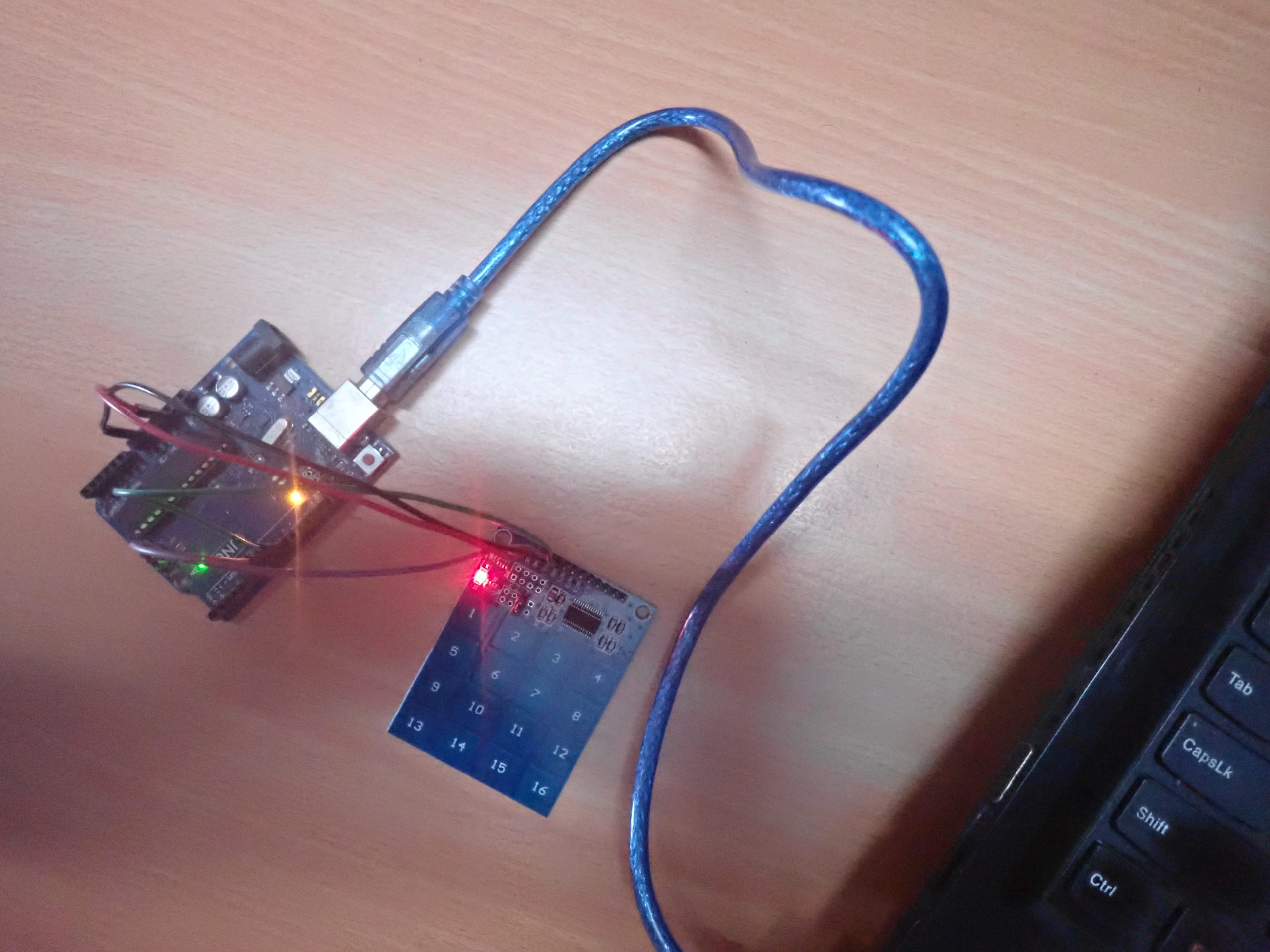
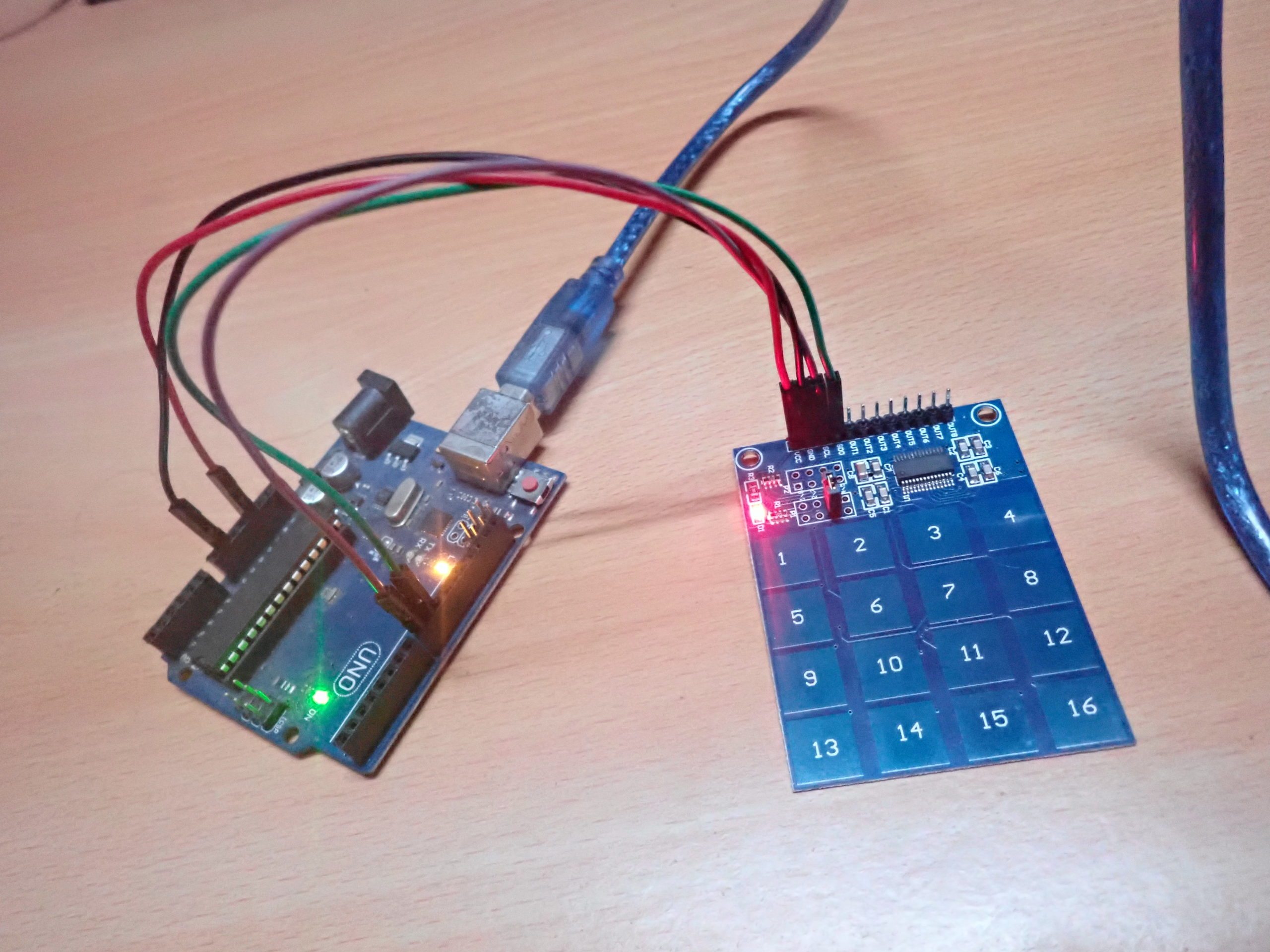
Results
In the next tutorial, we’ll learn how to interface an LDR sensor with Arduino.
Filed Under: Arduino, Microcontroller Projects

Questions related to this article?
👉Ask and discuss on EDAboard.com and Electro-Tech-Online.com forums.
Tell Us What You Think!!
You must be logged in to post a comment.