In the previous tutorial, we discussed scrolling long text strings on a character LCD using Arduino. However, it’s also possible to display custom characters on the LCD. These custom characters are user-defined and are stored in Character Generator RAM (CGRAM) of the LCD module.
The different LCD modules have different Display Data RAM (DDRAM) and CGRAM, which means several custom characters can be stored and displayed on the LCD modules.
Custom characters
The character LCDs support ASCII characters that serve as a standard set of characters. The patterns for the supported characters are already stored in the memory (CGROM) of the LCD module. For printing these standard characters, the controller simply needs to “pass” the associated data register value to the address counter of the LCD.
That data register value is, then, stored in the DDRAM and the address counter is updated (and increased or decreased depending on the direction of the text). When the LCD has to print a character, it reads the value from the DDRAM, compares it with CGROM, and prints the character by generating the stored pattern for that character.
Sometimes it’s necessary to print user-defined characters/icons on an LCD. For example, you may be using an LCD module in a communication device and need to print a custom character showing the status of the connectivity. A character LCD may be embedded in a battery-operated device and it may be necessary to display the level of charging by using a custom icon.
Or, depending on the application, it may be ideal to display different custom (user-defined) characters or icons on the LCD.
The LCD modules, apart from DDRAM, have the CGRAM to store user-defined characters. To generate a custom character/icon, it’s necessary for the controller needs to pass the entire character pattern to the LCD module. This character pattern is stored in the CGRAM of the LCD. A 16×2 LCD module typically has enough CGRAM to store a pattern for 8 characters/icons.
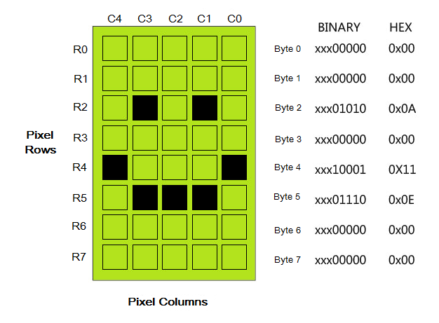
The pattern for custom characters is defined as a group of 7, 8, or 10 bytes, depending on the number of rows of pixels for each character on the LCD. Each byte represents a row of pixels that form the character. The bits of the byte represents the status of the pixels (i.e. whether the respective pixels will turn on or off).
The bit ‘1’ signifies that the pixel will turn on and the bit ‘0’ signifies that the pixel will turn off. Each byte is read from the Least Significant Bit (LSB), where only the first five or more represent the status of the pixels.
For example, on a 16×2 LCD, each character is printed as 5×8 dots. Therefore, 8 bytes (for 8 rows of pixels) are used to represent a character and 5 LSBs of each byte are used to turn on or off the pixels.
 As bytes representing a character are stored in RAM memory, the custom characters are stored temporarily on the LCD module. When the power to the LCD module is shut off, the CGRAM data is lost.
CGRAM
Most of the character LCD modules use an HD4478 controller. There can be a different LCD controller on an LCD module. To know what controller is used in an LCD module, simply refer to its data sheet.
Depending on the size of the character LCDs, they have different DDRAM and CGRAM. For example, a 16×2 LCD has 80 bytes of DDRAM and 64 bytes of CGRAM. As there are 8 rows of pixels for each character, the pattern for 8 characters of 5×8 dots can be stored on the CGRAM.
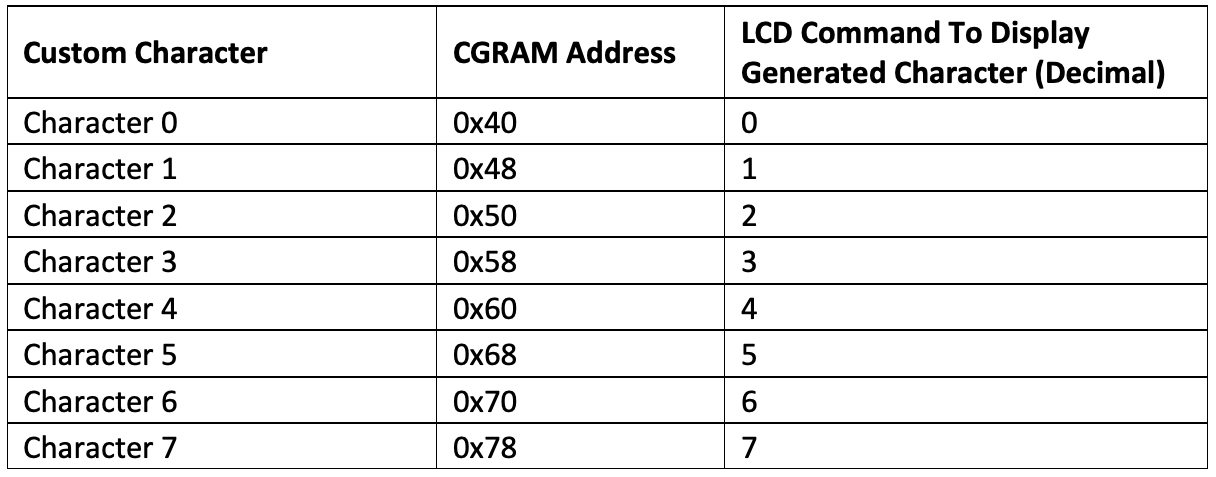
The CGRAM addresses start from 0x40. The first character is stored from address 0x40 to 0x47. This custom character can be printed at the current cursor position by sending the command ‘0’ to the LCD module. The second custom character is stored from the address 0x48 to 0x4F. It can be printed at the current cursor position by sending the command 1 to the LCD module.
This table lists the CGRAM addresses and commands to print them at current cursor position.
Generating custom characters
It’s fairly easy to create a custom character. Simply determine the pixel map of the character and, then, determine the bytes that should be written to the CGRAM to generate that character/icon. For a 16×2 LCD, which has 5×8 dots characters, the top three MSB for each byte can be ignored. The top three MSBs can be set to 0 in each byte while other bits can be set to 0 or 1, according to the pixels that should turn off or on.
In Embedded C (or any other programming language used to program the target microcontroller), these bytes can be grouped in an array. The bytes should be defined from the top to the bottom rows. If the bytes for any of the bottom row of pixels are not defined in the array, they’re assumed to be 0x00 by the programming language. This means the pixels on those rows will remain off.
Therefore, it is not necessary to explicitly define the bytes for every row, but just those for the top rows of pixels generating the character/icon.
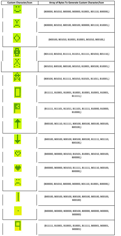
This table lists some of the custom characters/icons and the respective array of bytes required to generate them.
Generating custom characters
To create custom characters, typically the LCD command must first be set and the CGRAM address needs to be passed. Next, the LCD command to write data to the CGRAM needs to be passed.
After the CGRAM address is selected and the data is written to the CGRAM, the address counter is automatically updated — and either increased or decreased by one, depending on the entry mode. Afterward, all of the top bytes defining the character pattern must be written to the CGRAM to generate a custom character/icon.
When using Arduino, it’s even simpler to create a custom character/icon. The LiquidCrystal library on the Arduino platform has a function createChar() that creates custom characters and icons on an LCD. This function takes the position of the custom character and an array of bytes as an argument. The generated custom character can be flashed on an LCD at the current cursor position by using the write() or print() function.
The createChar() mskethod
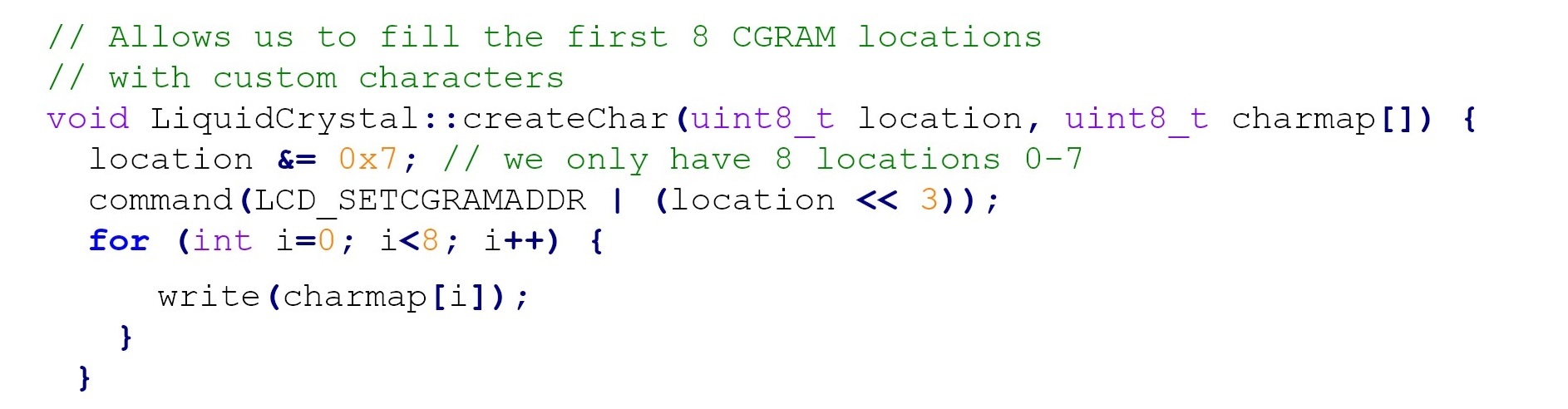
The createChar() function creates a custom character/icon for use on an LCD. Essentially, it writes a user-defined character pattern (a pixel map of the character) to a given CGRAM address.
The function has this syntax:
lcd.createChar(num, data)
This function takes two arguments:
1. A number that signifies the position of custom character
2. An array of bytes that determines the pixel map of the character.
The position of the character is specified as a number. For example, in the case of 16×2 LCD, 8 custom characters can be defined and their position can be 0 to 7.
The character with the position 0 is stored at the CGRAM address 0x40, and the character with the position 1 is stored at the CGRAM address 0x48, and so on. If a position greater than 7 is passed in the function, the modulus of that number by 8 is used as the position by the function. For example, if the position of the character is passed as 8, then the position of the character will be 0.
The array of bytes passed as the argument to define the character must have the bytes defined for all of the top rows of the pixels forming the character.
The createChar() method has this source code:
The write() method
The write() function writes a character on an LCD. The character is written (displayed) at the current cursor position and the cursor is moved right or left according to the direction of text on LCD.
The function has this syntax:
lcd.write(data)
If the data passed is a string (quoted in double or single quotes) of ASCII characters, it is written as such. If it’s a number, the character corresponding to that position in the CGRAM is written on the LCD.
The write() method has this source code:

The print() method
The print() method is used to print text to an LCD. If a custom character has to be written on the LCD using the print() method, then the char() function (with the position of the custom character as the argument), must be passed as the argument of the print() function.
Here’s a valid example of printing a custom character on an LCD:
lcd.print(char(0));
Recipe: Displaying custom characters on an LCD
In this recipe, we will print some custom characters on a 16×2 LCD.
Components required
1. Arduino UNO x1
2. A 16×2 character LCD x1
3. A 10K Pot x1
4. A 330-Ohms Resistor or any low-value resistor x1
5. Breadboard x1
6. Male-to-Male Jumper Wires or Connecting Wires
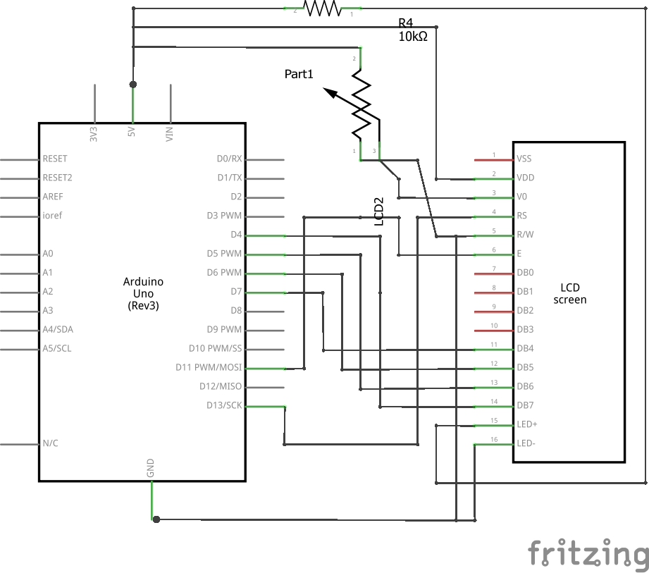
Circuit connections
The LCD module used in this project is JHD162A. This is a 16×2 LCD module with 5×8 character dots. The LCD module has a 16-pin interface. The LCD is interfaced with Arduino in a 4-bit mode.
- Pin 1 (GND) and 16 (LED) of the LCD module are connected to the ground.
- Pin 2 (VCC) is connected to the VCC.
- Pin 15 (LED+) of the LCD module is then connected to the VCC via a small-value resistor.
- Pin 3 (VEE) is connected to the variable terminal of a pot while the fixed terminals of the pot are connected to the ground and the VCC.
- The R/W pin is connected to the ground because Arduino will only write data to the LCD module.
- The RS, EN, DB4, DB5, DB6, and DB7 pins of LCD are connected to pins 13, 11, 7, 6, 5, and 4 of Arduino UNO, respectively.
- The breadboard is supplied to the ground, the 5V supply rail from one of the ground pins and the 5V pin of the Arduino UNO, respectively.
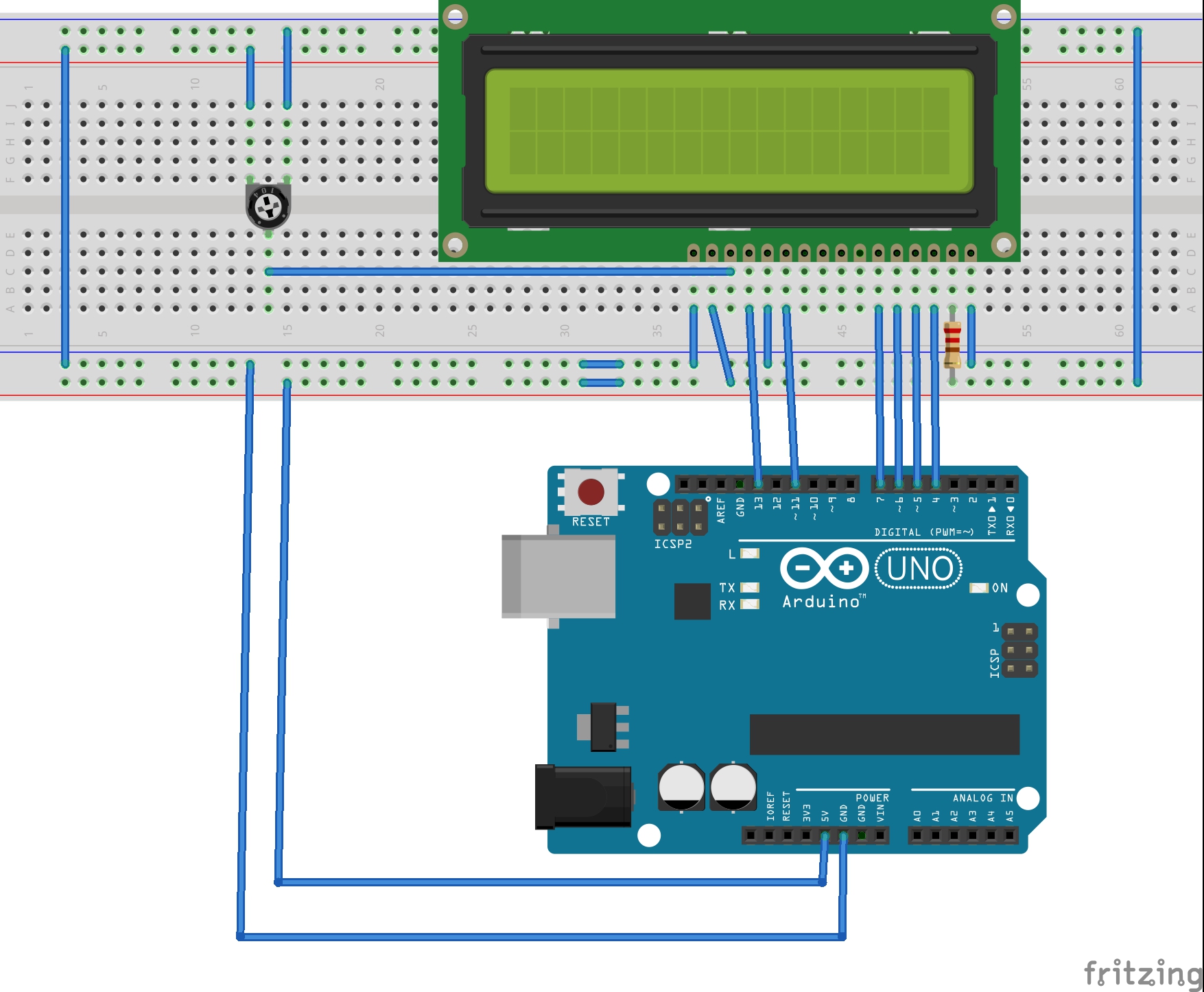
Circuit diagram
Arduino sketch
How the project works
The LCD module is connected with Arduino in 4-bit mode. The LCD is first initialized and the display is cleared to get rid of any garbage values in the DDRAM.
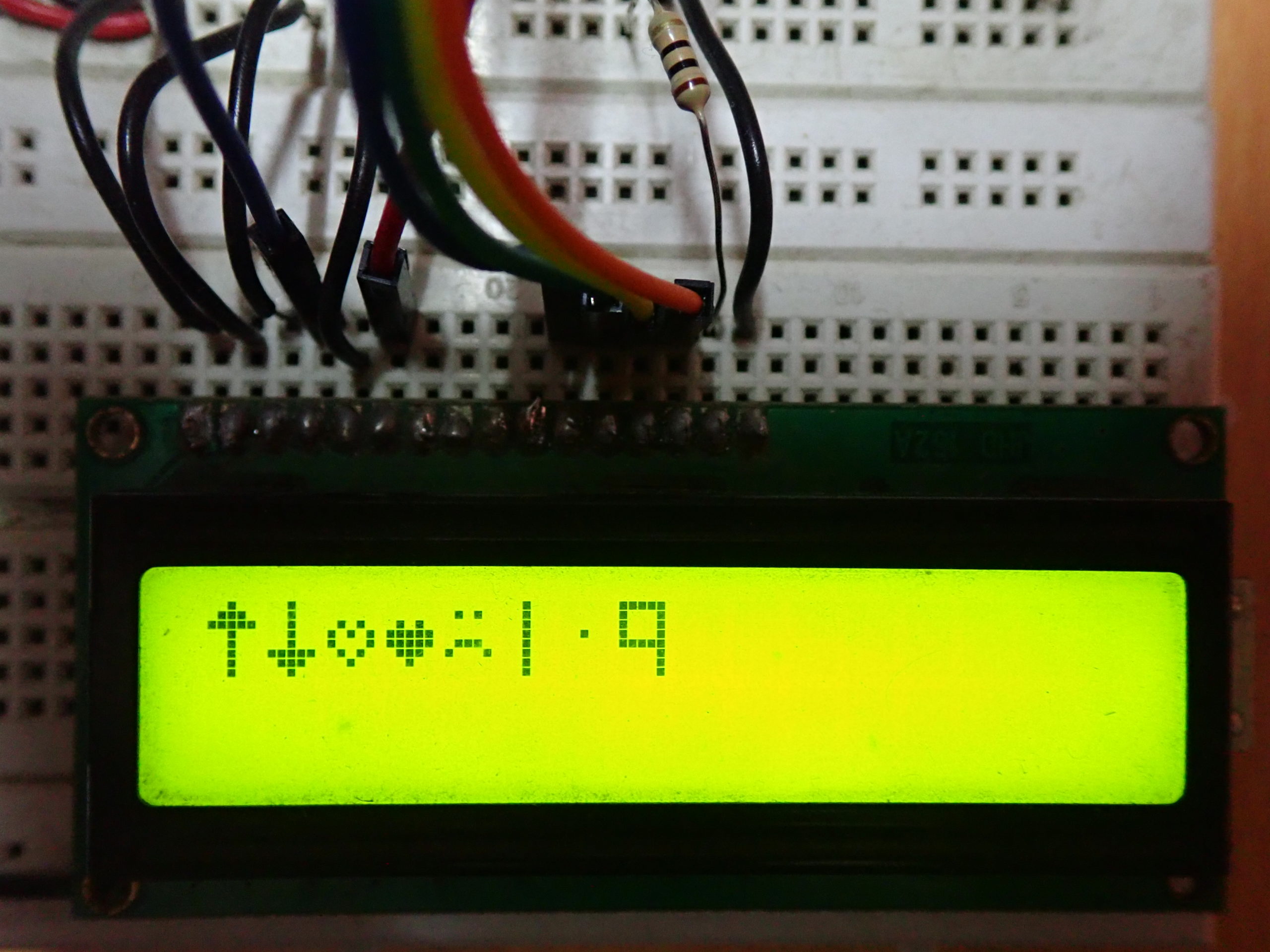
The patterns for 16 different custom characters are then generated by defining their pixel maps as arrays. Eight of these custom characters can be displayed on the LCD at one time. This is because 64 bytes of the CGRAM of the 16×2 LCD can store a pattern for only 8 characters at any time.
The 8 custom characters are generated by defining their character maps. The cursor position on the LCD is set from column 0 of line 0 to column 7 of line 0, and each character is displayed one by one. Then, the next 8 custom characters are generated and they’re displayed on line 0 of the LCD at the cursor positions from columns 0 to 7.
Thereafter, the embedded program starts iterating and two sets of 8 custom characters keep displaying on the LCD, one after the other.

Programming guide
The LiquidCrystal.h library is imported in the code. Then, an object defined by the “lcd” is defined by the LiquidCrystal class.
#include <LiquidCrystal.h>
//LiquidCrystal lcd(RS, E, D4, D5, D6, D7);
LiquidCrystal lcd(13, 11, 7, 6, 5, 4);
The pixel maps of the 16 different custom characters are defined as array objects of the global scope as follows:
byte
c1[8]={B00000,B01010,B00000,B00000,B10001,B01110,B00000,};
//Smile-1
byte
c2[8]={B00000,B01010,B00100,B00100,B00000,B01110,B10001,};
//Smile-2
byte
c3[8]={B00100,B01010,B10001,B10001,B01010,B00100,}; //Diamond
byte
c4[8]={B01110,B01010,B11111,B11011,B11111,B01010,B01110,}; //Brick
byte
c5[8]={B01010,B00100,B00100,B01010,B10001,B00100,B10001,}; //Hour-glass
byte
c6[8]={B00100,B01010,B11111,B01010,B10101,B11011,B10001,}; //Hut
byte
c7[8]={B11111,B10001,B10001,B10001,B10001,B10001,B10001,B11111,}; //Rectangle
byte
c8[8]={B11111,B11101,B11011,B11101,B11111,B10000,B10000,B10000,}; //Flag-1
byte
c9[8]={B00100,B01110,B11111,B00100,B00100,B00100,B00100,B00100,}; //Up-Arrow
byte
c10[8]={B00100,B00100,B00100,B00100,B00100,B11111,B01110,B00100,}; //Down-Arrow
byte
c11[8]={B00000,B00000,B01010,B10101,B10001,B01010,B00100,B00000,}; //Blank-Heart
byte
c12[8]={B00000,B00000,B01010,B11111,B11111,B01110,B00100,B00000,}; //Full-Heart
byte
c13[8]={B00000,B01010,B00000,B00000,B01110,B10001,B00000,}; //Smile-Sad
byte
c14[8]={B00100,B00100,B00100,B00100,B00100,B00100,B00100,B00100}; //Pole
byte
c15[8]={B00000,B00000,B00000,B00100,B00000,B00000,B00000,B00000}; //Dot
byte
c16[8]={B11111,B10001,B10001,B10001,B11111,B00001,B00001,B00001}; //Flag-2
In the setup() function, the LCD is initialized to the 16×2 size by using the begin() method.
The LCD is also cleared once to get rid of any garbage values as follows:
void setup()
{
lcd.begin(16, 2);
lcd.clear();
}
In the loop() function, the first 8 custom characters are generated using the customChar() method. The cursor position is set by using the setCursor() method. Each character is printed on the LCD by using the print() method at the cursor positions of column 0 to 7 of line 0, one after the other.
After the printing of the 8 characters, a two-second delay is provided using the delay() function. Then, the LCD is cleared by using the clear() method.
void loop()
{
lcd.createChar(0 , c1); //Creating custom characters in CG-RAM
lcd.createChar(1 , c2);
lcd.createChar(2 , c3);
lcd.createChar(3 , c4);
lcd.createChar(4 , c5);
lcd.createChar(5 , c6);
lcd.createChar(6 , c7);
lcd.createChar(7 , c8);
lcd.setCursor(0 ,0);
lcd.print(char(0));
lcd.setCursor(1 ,0);
lcd.print(char(1));
lcd.setCursor(2 ,0);
lcd.print(char(2));
lcd.setCursor(3 ,0);
lcd.print(char(3));
lcd.setCursor(4 ,0);
lcd.print(char(4));
lcd.setCursor(5 ,0);
lcd.print(char(5));
lcd.setCursor(6 ,0);
lcd.print(char(6));
lcd.setCursor(7 ,0);
lcd.print(char(7));
delay(2000);
lcd.clear();
Similarly, the next set of 8 custom characters is generated and printed on line 0 of the LCD. It should be noted that we have created and displayed custom characters in the loop() function. So, if the power supply to the LCD module is interrupted for any reason, the custom characters will regenerate and reprint on the LCD.
If we would have generated the custom characters in the setup() function, that code would have only run once. In that case, if the power supply to the LCD module was somehow interrupted, the character pattern for the custom characters would have been lost and garbage values would have displayed on the LCD.
Additionally, we are printing more than 8 custom characters on the LCD even though only 8 custom characters can be generated and printed. This is another reason that we generated the custom characters in the loop() function.
Do it yourself
In this recipe, you learned to generate custom characters and print them on a 16×2 character LCD. Now think of other possible custom characters and icons, draw their pixel maps (in 5×8 dots), and determine the bytes that should be written to the CGRAM to generate them.
You can modify the above Arduino sketch to print custom characters and icons. You can also try generating character patterns for your regional language or types of common icons — such as a battery status, Wi-Fi, smiley, or other glyphs. Do so until you are limited by the 5×8 dots matrix!
In the next tutorial, we’ll learn how to interface an LM-35 temperature sensor with Arduino.
Demonstration video
Filed Under: Arduino, Microcontroller Projects

Questions related to this article?
👉Ask and discuss on EDAboard.com and Electro-Tech-Online.com forums.
Tell Us What You Think!!
You must be logged in to post a comment.