Any machine programmable by a computer and capable of performing defined tasks is called a robot. There are many types of robots and robotic cars are one among them. The robotic cars are generally used to reach out at places where it may be dangerous for humans to reach or stay due to physical or environmental conditions. The robotic cars may be used for surveillance or for performing some mechanical tasks in a remote location. The robotic cars make the most sense when they are controlled by some wireless technology. In this project, a robotic car is designed to sense ambient temperature, humidity, light intensity and detect obstacles in the path. The robot is controlled by a mobile app which connects with the robot through Bluetooth.
For wireless connectivity, HC-05 Bluetooth module is used in the robot circuit and the mobile app runs on any smartphone which has the Bluetooth inbuilt. The circuit for the Robot is built on Arduino UNO so the Arduino board is controlling the robot functionality. The Arduino board reads data from various sensors (DHT-11 Temperature and Humidity Sensor, LDR Sensor, Ultrasonic Range Finder Sensor), controls two DC motors through L293D motor driver IC and manage communication with the mobile app through Bluetooth module. The Arduino sketch is written on Arduino IDE and burnt to the board using AVR Dude.
The mobile app is designed using MIT’s App Inventor. MIT App Inventor is a Visual Scripting Platform for creating mobile apps. It allows creating an app by integrating graphical building blocks together. The platform is designed for non-programmers to develop simple mobile apps by just graphically putting together the graphical elements and logical elements.
Components Required –
• Arduino UNO
• L293D motor driver IC
• HC-SR 04 sensor
• HC-05 Bluetooth module
• DTH11 sensor
• LDR sensor
• 7805 voltage regulators
• 5 mm LED
• 1K ohm Resistor
Block Diagram –
Fig. 1: Block Diagram of Mobile App controlled Arduino Robot
Circuit Connections –
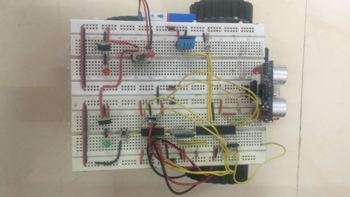
Fig. 2: Prototype of Mobile App controlled Arduino Robot
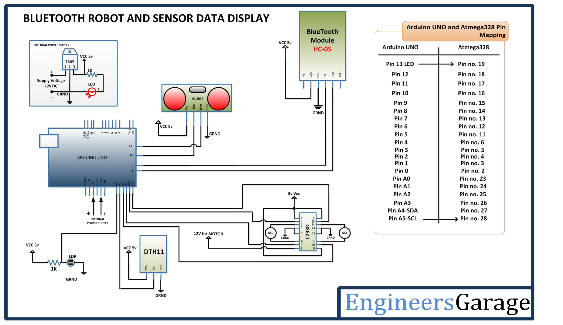
The mobile app designed in this project can run on any smartphone with Bluetooth functionality. For building the robot, different sensors and the motor driver circuit is interfaced to the Arduino UNO. The circuit connections are as follows –
Power Supply – In the circuit, Arduino board and other ICs need a 5V regulated DC for their operation. An 18V battery is used as the primary source of power. The supply from the battery is regulated to 5V using 7805 voltage regulator IC. The pin 1 of the voltage regulator IC is connected to the anode of the battery and pin 2 of it is connected to ground. The respective voltage output is drawn from pin 3 of the 7805 IC. A LED along with a 10K Ω pull-up resistor is also connected between common ground and output pin to get a visual hint of supply continuity.
DHT-11 Temperature and Humidity Sensor – The DHT -11 sensor reads the ambient temperature and humidity and relays the data to the microcontroller as digital data. The data pin of temperature and humidity sensor DHT11 is connected to pin A1 of the Arduino board and VCC and ground are connected to the common VCC and ground respectively.
LDR Sensor – The LDR is used to sense the intensity of light. The sensor is connected to the A0 pin of Arduino board. The sensor is connected in a voltage divider circuit. The LDR provides an analog voltage which is converted to digital reading by the in-built ADC of the controller.
HC-SR04 Ultrasonic Sensor – The ultrasonic sensor is connected to pins 10 and 11 of the Arduino board. The ultrasonic sensor has four pins – Ground (Pin 1), Echo (Pin 2), Trigger (Pin 3) and Trigger. The VCC and ground pins are connected to common VCC and Ground respectively. The Echo pin is connected to pin 11 of the Arduino board while Trigger pin is connected to pin 10 of Arduino board. The ultrasonic sensor works on the principle of echo of sound waves. When a HIGH pulse of 10 u sec is passed to the trigger pin of the sensor, it transmits eight 40 KHz waves of HIGH Sonic Pulse shots back to back. A High pulse signal is out from the echo pin as the ultrasonic wave is transmitted.
This wave when collides with an obstacle, it is reflected back and detected by the sensor. On detecting the wave again, the High pulse signal from the echo pin of the sensor is terminated. The signal received from the echo pin is analog in nature. The distance from the obstacle can be measured by measuring the high time of the echo pin. This is the time between the transmission and reflection back of the sonic wave. The distance is given by the formulae –
Test distance = (high level time × velocity of sound (340M/S)) / 2
The time multiplied by velocity is divided by 2 as the time taken is for sonic wave to reach obstacle and return back. Therefore the distance measurement in cm can be given by the formulae –
Test distance = (high level time × velocity of sound (340M/S)) / 2
= (high level time(microsecond) × velocity of sound (340M/S)) / 2
= high level time x 340/2000000 m
= high level time x 34000/2000000 cm
= high level time x 34/2000 cm
The ultrasonic sensor outputs the high pulse from pin 2 which is detected at the pin 11 of the Arduino Board. The program code measures the pulse duration and digitizes it to a distance value using the formulae stated above.
HC-05 Bluetooth Module – HC-05 Bluetooth module is serial port protocol module. It operates on ISM band 2.4GHz with V2.0+EDR (Enhanced data date). It can work in both Master and slave modes. The Bluetooth module has six pins – Enable, VCC, Ground, Transmit Data (TxD), Receive Data (RxD) and State. The Enable and State pin are unused and so not connected in the circuit. The VCC and Ground pins are connected to the common VCC and Ground respectively. The TxD and RxD pins of the module are connected to the pins 2 and 3 of the Arduino board respectively.
L293D DC Motor Driver IC – The L293D is the motor control driver IC. It has 16 pins with following pin configuration:
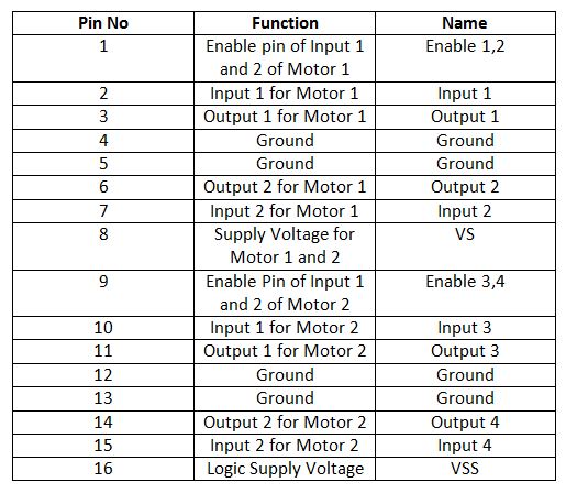
Fig. 3: Table listing pin configuration of L293D Motor Driver IC
The pin 4, 5, 13 and 12 of the L293D are grounded while pin 1, 16 and 9 are connected to 5V DC and pin 8 is connected to 9V DC. The pins 15, 2, 7 and 10 of the motor driver IC are connected to pins SCL, SDA, A3 and A2 of Arduino UNO.
The L293D IC controls the DC Motors according to the following truth tables:
Fig. 4: Truth Table of L293D Motor Driver IC
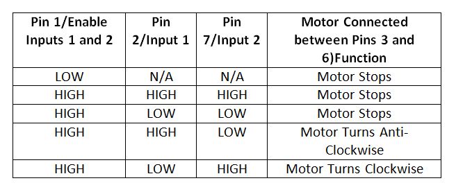
Fig. 5: Truth Table of L293D Motor Driver IC
How the circuit works –
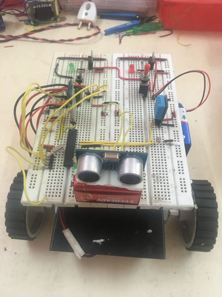
Fig. 6: Image of Mobile App controlled Arduino Robot
Once the robot is powered by the battery, it needs to be paired with the mobile app. The mobile app is built on MIT App Inventor and is named “BT-Robot” in the project. The app can be downloaded from Engineers Garage or built from scratch on MIT App Inventor. As the app is launched, it searches for available devices for pairing. The Bluetooth Module with its MAC address will be visible on the app’s activity and pairing can be initiated by just tapping the available Bluetooth module. The Bluetooth module will be automatically paired with the mobile app.
Once the pairing is done, the Arduino starts reading data from the sensors and sending it to the mobile app. The data is serially pushed to the Bluetooth module which automatically transfers it to the paired Bluetooth device, smart phone in this case. First, the DHT11 Temperature and Humidity Sensor, which is a digital sensor with inbuilt capacitive humidity sensor and Thermistor is read. It relays a real-time temperature and humidity reading every 2 seconds. The sensor operates on 3.5 to 5.5 V supply and can read temperature between 0° C and 50° C and relative humidity between 20% and 95%. The DHT 11 Sensor sends data in the digital form to a controller pin on a one-wire protocol which must be implemented on firmware side.
First, the data pin is configured to input and a start signal is sent to it. The start signal comprises of a LOW for 18 milliseconds followed by a HIGH for 20 to 40 microseconds followed by a LOW again for 80 microseconds and a HIGH for 80 microseconds. After sending the start signal, the pin is configured to digital output and 40-bit data comprising of the temperature and humidity reading is latched out. Of the 5-byte data, the first two bytes are an integer and decimal part of reading for relative humidity respectively, third and fourth bytes are an integer and decimal part of reading for temperature and the last one is checksum byte. The one-wire protocol is implemented on the firmware using an open-source library available for Arduino.
The LDR sensor output an analog voltage at the interfaced controller pin. The analog voltage is read and digitized using inbuilt ADC channel. The analogRead() function is used to read analog voltage at the controller pin.
For reading data from the ultrasonic sensor, first a pulse has to be sent to the trigger pin of the sensor and then the analog voltage is read from the echo pin. The analog voltage is converted to digital reading using inbuilt ADC channel and converted to distance measurement using the formulae stated above. The data from all the sensors is sent to the mobile app on which it is displayed in real-time.
The mobile app can send commands for the movement of the robot for forward, backward, left and right motion. These commands are received serially from the Bluetooth module and interpreted to set the input pins on L293D motor driver IC.
In the robot circuit considering the two-wheel drive either the front or rear possible drive, right-hand side (RHS) motor is connected between pins 3 and 6 and left-hand side (LHS) motor is connected between pin 11 and 14 of the L293D. The RHS motor is controlled by pin 2 and 7 of the L293D while LHS motor is controlled by pin 10 and 15 of L293D. Hence, to move the robot in the different direction following digital outputs are required at the L293D pins:
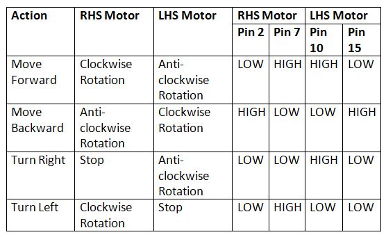
Fig. 7: Logic Table of L293D Motor Driver IC for Mobile App controlled Arduino Robot
So to drive robot forward in this two-wheel drive, RHS motor needs to be rotated clockwise and LHS motor needs to be rotated anticlockwise. This is done by passing LOW signals to pin 2 and 15 of L293D and HIGH signal to pin 7 and 10 of L293D according to the truth table. To drive robot backward (applicable to two wheel drive) RHS motor needs to be rotated anti-clockwise and LHS motor needs to be rotated clockwise. This is done by passing LOW signals to pin 7 and 10 of L293D and HIGH signal to pin 2 and 15 of L293D according to the truth table.
To turn the robot right, RHS motor has to be stopped and LHS motor needs to be rotated anti-clockwise. This is done by passing LOW signals to pin 2, 7 and 15 of L293D and HIGH signal to pin 10 of L293D according to the truth table. To turn the robot left, LHS motor has to be stopped and RHS motor needs to be rotated in clockwise direction. This is done by passing LOW signals to pin 2, 10 and 15 of L293D and HIGH signal to pin 7 of L293D according to the truth table. The motors are stopped in the project by giving both control inputs of L293D for each motor a LOW logic.
The L293D pins are interfaced with the Arduino pins in the following manner –

Fig. 8: Table listing circuit connections between Arduino and L293D Motor Driver IC
Check out the Arduino code to learn how it reads data from the sensors and transfer it to the Bluetooth module and how it reads commands from the Bluetooth module and change digital logic at L293D pins to control DC motors.
Programming Guide –
The softwareSerial library is imported for serial communication with the Bluetooth module and DHT library is imported to handle DHT sensor. A variable is declared and assigned a pin to denote LED indicating Bluetooth connectivity. Variables are declared and assigned controller pins for DHT sensor, LDR sensor, and ultrasonic sensor. Variables are declared and assigned controller pins to denote motor driver IC connections. Some variables are declared to store sensor values and objects of DHT type and Virtual serial type are instantiated.
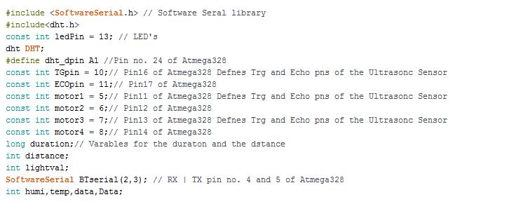
Fig. 9: Screenshot of Initialization in Arduino Code for Mobile operated Robotic Car
The setup() function is called which runs for once after the controller is powered on. In the function, baud rate for serial communication with the Bluetooth module is set to 9600 baud per second. The pins connected to trigger pin of the ultrasonic sensor, LED and motor driver IC are set to digital output while pins connected to echo pin of the ultrasonic sensor is set to digital input using pinMode() function. Some initial messages are sent to the Bluetooth module for display on the mobile app using Serial.println() function.
Fig. 10: Screenshot of Setup Function in Arduino Code for Mobile operated Robotic Car
The loop() function is called which iterates infinitely. Any data available from the Bluetooth module is checked using the available method on a virtual serial object and if available is read using read() method and stored to variable Data. The data from DHT sensor is read using humidity() and temperature() methods on DHT object and stored in variables humid and temp respectively. The distance from the ultrasonic sensor is read using user-defined function FindDistance() and value of LDR sensor is read using analogRead() method. The values of the sensors are sent to the Bluetooth module via the virtual serial port. The data from the Bluetooth module is read and compared with strings ‘F’, ‘B’, ‘L’, ‘R’ and ‘S’ for implementing motor control logic for the forward movement, backward movement, left turn, right turn and stopping the robot.
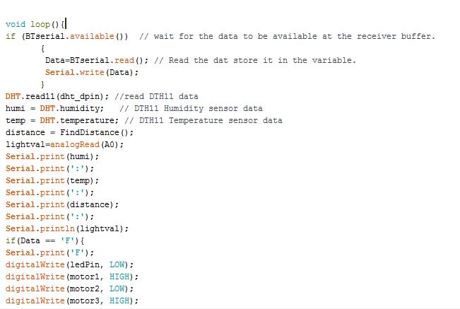
Fig. 11: Screenshot of Loop Function in Arduino Code for Mobile operated Robotic Car
The FindDistance() function is used to sense analog voltage from the ultrasonic sensor and calculate distance according to the sensor’s datasheet. First, a pulse is generated at trigger pin and pulse duration in the form of analog voltage is read using pulseIn() method and stored to variable duration. The pulse duration is converted to distance measurement using standard conversion formulae. The value of the distance is returned by the function.
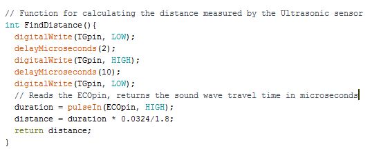
Fig. 12: Screenshot of Find Distance Function in Arduino Code for Mobile operated Robotic Car
The complete Arduino code for Mobile App Controlled Robot Car can be found in the source code tab.
The mobile app is developed on MIT App Inventor. The block representing code for searching and connecting with the Bluetooth module is as follow –
Fig. 13: Screenshot of MIT App Inventor showing different operational blocks of Robot Controlling App
The block representing sensor data display on the app is as follow –
Fig. 14: Screenshot of MIT App Inventor showing block for sensor data display
The block representing Bluetooth connection for controlling robot motion and various buttons for robot movement is as follow –
Fig. 15: Screenshot of MIT App Inventor showing block for bluetooth connection
The app can be built on App Inventor or can also be downloaded from Engineers Garage.
Note: The rar file for BT Robot app can be found in the attachment given below.
Project Source Code
###
//Program to#include <SoftwareSerial.h> // Software Seral library #include<dht.h> const int ledPin = 13; // LED's dht DHT; #define dht_dpin A1 //Pin no. 24 of Atmega328 const int TGpin = 10;// Pin16 of Atmega328 Defnes Trg and Echo pns of the Ultrasonc Sensor const int ECOpin = 11;// Pin17 of Atmega328 const int motor1 = 5;// Pin11 of Atmega328 Defnes Trg and Echo pns of the Ultrasonc Sensor const int motor2 = 6;// Pin12 of Atmega328 const int motor3 = 7;// Pin13 of Atmega328 Defnes Trg and Echo pns of the Ultrasonc Sensor const int motor4 = 8;// Pin14 of Atmega328 long duration;// Varables for the duraton and the dstance int distance; int lightval; SoftwareSerial BTserial(2,3); // RX | TX pin no. 4 and 5 of Atmega328 int humi,temp,data,Data; void setup() { Serial.begin(9600); BTserial.begin(9600); pinMode(TGpin, OUTPUT); // Sets the TGpin as an Output pinMode(ECOpin, INPUT); // Sets the ECOpin as an input pinMode(ledPin, OUTPUT); digitalWrite(ledPin, HIGH); pinMode(motor1, OUTPUT); pinMode(motor2, OUTPUT); pinMode(motor3, OUTPUT); pinMode(motor4, OUTPUT); Serial.println("Engineers Garage"); Serial.println(" BT ROBOT "); } void loop(){ if (BTserial.available()) // wait for the data to be available at the receiver buffer. { Data=BTserial.read(); // Read the dat store it in the variable. Serial.write(Data); } DHT.read11(dht_dpin); //read DTH11 data humi = DHT.humidity; // DTH11 Humidity sensor data temp = DHT.temperature; // DTH11 Temperature sensor data distance = FindDistance(); lightval=analogRead(A0); Serial.print(humi); Serial.print(':'); Serial.print(temp); Serial.print(':'); Serial.print(distance); Serial.print(':'); Serial.println(lightval); if(Data == 'F'){ Serial.print('F'); digitalWrite(ledPin, LOW); digitalWrite(motor1, HIGH); digitalWrite(motor2, LOW); digitalWrite(motor3, HIGH); digitalWrite(motor4, LOW); } if(Data == 'B'){ Serial.print('B'); digitalWrite(ledPin, LOW); digitalWrite(motor2, HIGH); digitalWrite(motor1, LOW); digitalWrite(motor4, HIGH); digitalWrite(motor3, LOW); } if(Data == 'L'){ Serial.print('L'); digitalWrite(ledPin, LOW); digitalWrite(motor1, HIGH); digitalWrite(motor2, LOW); digitalWrite(motor3, LOW); digitalWrite(motor4, HIGH); } if(Data == 'R'){ Serial.print('R'); digitalWrite(ledPin, LOW); digitalWrite(motor1, LOW); digitalWrite(motor2, HIGH); digitalWrite(motor3, HIGH); digitalWrite(motor4, LOW); } if(Data == 'S'){ Serial.print('S'); digitalWrite(ledPin, HIGH); digitalWrite(motor1, LOW); digitalWrite(motor2, LOW); digitalWrite(motor3, LOW); digitalWrite(motor4, LOW); } BTserial.print(lightval); BTserial.println("%"); BTserial.print("|"); BTserial.print(temp); BTserial.println("C"); BTserial.print("|"); BTserial.print(humi); BTserial.println("%"); BTserial.print("|"); BTserial.print(distance); BTserial.println("cm"); delay(700); } // Function for calculating the distance measured by the Ultrasonic sensor int FindDistance(){ digitalWrite(TGpin, LOW); delayMicroseconds(2); digitalWrite(TGpin, HIGH); delayMicroseconds(10); digitalWrite(TGpin, LOW); duration = pulseIn(ECOpin, HIGH); // Reads the ECOpin, returns the sound wave travel time in microseconds distance = duration * 0.0324/1.8; return distance; }###
Circuit Diagrams
Project Video
Filed Under: Electronic Projects
Filed Under: Electronic Projects


Questions related to this article?
👉Ask and discuss on EDAboard.com and Electro-Tech-Online.com forums.
Tell Us What You Think!!
You must be logged in to post a comment.