
Fig. 1: Image of an LED circuit on breadboard
Image above shows a simple circuit that glows an LED when connected to power supply.. Connecting LED directly to the power supply will damage it, hence aresistance of suitable value must be connected in series for its proper operation. Following the standard color convention,red wire serves as the positive connection lead while black one is the common or negative lead. In this tutorial, we will be measuring DC voltage and current in the circuit.
How to Measure Voltage using Multimeter

Fig. 2: Image of LEd circuit working on a breadboard
9V DC supply is used to power the circuit. The LED will glow as soon as we connect the wires to the power source. Make sure that all the connections are tight. If the LED doesn’t glow after connecting the supply, then check the connection and the LED.
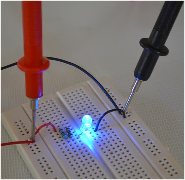
Fig. 3: Image showing multimeter probes connected to LED circuit for voltage testing
Step 1:Connect the testing leads to the multimeter.
Step 2: Turn the knob to the DV voltage segment in the multimeter at 40DCV.
Step 3:Connect the probes in the circuit according to the polarity.
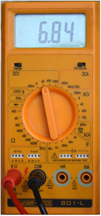
Fig. 4: Image of multimeter showing DC voltage reading from LED circuit
Step 4: Power on the Multimeter.
Step 5: Note down the reading.
The multimeter will show the voltage across the circuit. For example the voltage across this circuit is 6.84V
How to Measure Current using Multimeter:
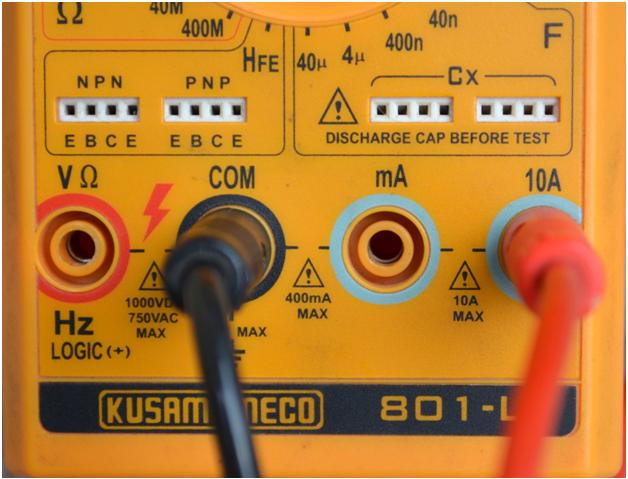
Fig. 5: Image showing connection of probes in Multimeter for measuring current
Multimeter has different procedure for measuring current. Current can be measured in the range ofmilliamperes (400mA max.) to Ampere (10A max.) as shown in the above image.
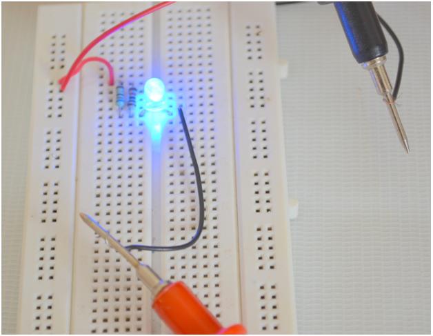
Fig. 6: Image showing multimeter probes connected to LED circuit for measuring current
Multimeter works like an ammeter when ammeter.
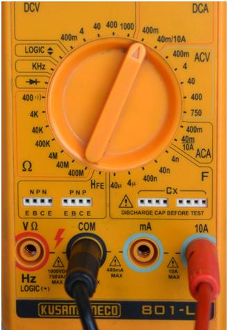
Fig. 7: Image showing multimeter set to DCA region
Step1: Turn the knob on the DCA section.
Step2:Choose the current rating. The meter will display current in both rating.
Step3: Connect the testing leads to the current measurement setting.
Step4: Turn ON the multimeter.
Step 5: The multimeter will display the current in the circuit shown as shown in the image below.
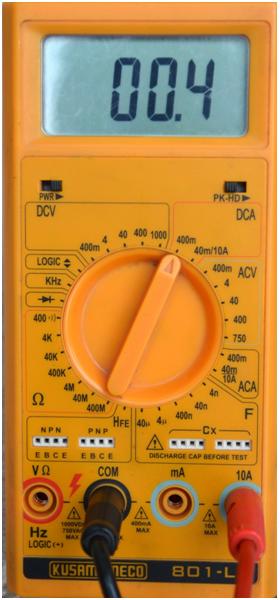
Fig. 8: Image of multimeter showing DC current reading from LED circuit
As shown, 0.4 mA of current flows into the ciruit.
Filed Under: Tutorials


Questions related to this article?
👉Ask and discuss on Electro-Tech-Online.com and EDAboard.com forums.
Tell Us What You Think!!
You must be logged in to post a comment.