Step 1: Understanding Diode

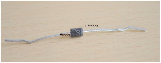
Fig. 1: Image of a Diode
Diode has two terminals Anode (+) and Cathode (-). Terminals can be identified by the shaded portion at the end of the diode. Terminal near the shaded portion is Cathode (-) and other one is anode (+).
Diode can be tested with the help of Diode function of the multimeter

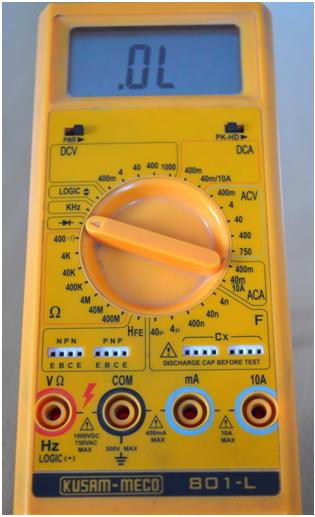
Fig. 2: Image showing DMM connection on Multimeter
{C}{C}{C} ·Power ON the multimeter
{C}{C}{C} ·Turn the knob towards the “Diode Function”
{C}{C}{C} ·The Digital Meter will show no reading as there are no terminals connected.
Step 3:Testing Leads Connection

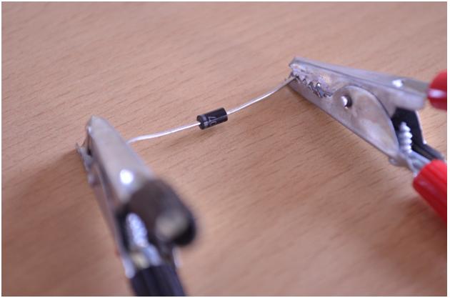
Fig. 3: Image showing crocodile probes connected to Diode
{C}{C}{C} ·Connect the leads in forward biasing i.e. Positive to the Anode and Negative to the Cathode.
{C}{C}{C} ·Connections should be tight and neat
{C}{C}{C} ·After connecting note down the reading.

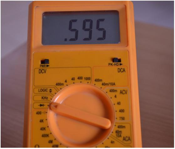
Fig. 4: Image showing multimeter displaying Forward Voltage Drop of the Diode
The multimeter will show theforward voltage drop between the two testing leads.
Filed Under: Tutorials


Questions related to this article?
👉Ask and discuss on Electro-Tech-Online.com and EDAboard.com forums.
Tell Us What You Think!!
You must be logged in to post a comment.