Engineers Garage

  • Projects and Tutorials
    • Electronic Projects
      • 8051
      • Arduino
      • ARM
      • AVR
      • PIC
      • Raspberry pi
      • STM32
    • Tutorials
    • Circuit Design
    • Project Videos
    • Components
  • Articles
    • Tech Articles
    • Insight
    • Invention Stories
    • How to
    • What Is
  • News
    • Electronic Products News
    • DIY Reviews
    • Guest Post
  • Forums
    • EDABoard.com
    • Electro-Tech-Online
    • EG Forum Archive
  • Digi-Key Store
    • Cables, Wires
    • Connectors, Interconnect
    • Discrete
    • Electromechanical
    • Embedded Computers
    • Enclosures, Hardware, Office
    • Integrated Circuits (ICs)
    • Isolators
    • LED/Optoelectronics
    • Passive
    • Power, Circuit Protection
    • Programmers
    • RF, Wireless
    • Semiconductors
    • Sensors, Transducers
    • Test Products
    • Tools
  • EE Resources
    • DesignFast
    • LEAP Awards
    • Oscilloscope Product Finder
    • White Papers
    • Webinars
  • EE Learning Center
    • Design Guides
      • WiFi & the IOT Design Guide
      • Microcontrollers Design Guide
      • State of the Art Inductors Design Guide
  • Women in Engineering

Phase Lock Loop

By Ashuthosh Bhat

Phase lock loop is one of the most essential building blocks of any communication system. It locks to particular frequency and generates output. It is used in electronics frequency control like in satellite communication, air born navigation, radar and FM communications. PLL are used in

  • Frequency multiplication or division

  • AM demodulation

  • FM demodulation

  • FSK demodulation

  • Satellite tracking system

The phase lock loop (PLL) consist of phase comparator, low pass filter and a voltage controlled oscillator (VCO) in feedback path. The phase comparator compares frequency and phase of input signal with VCO output signal. It generates +ve or –ve signal if there is difference in frequency or phase between input signal and VCO output. This voltage is further filtered by LPF and DC voltage is given to VCO. So VCO will increase or decrease its output signal frequency. When there is a match in frequency and phase of both these signals, comparator output is 0 and PLL is said to be locked at that frequency.

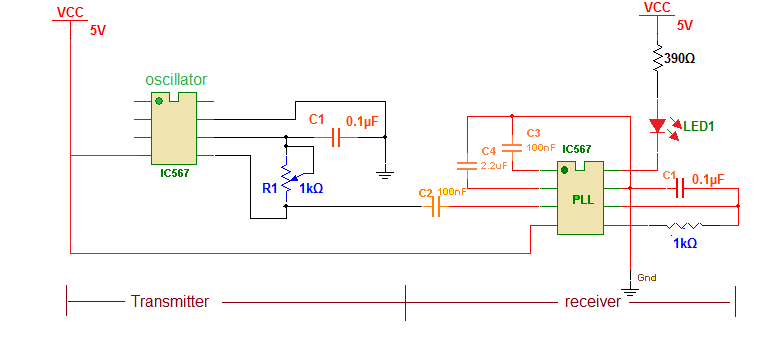
The given circuit demonstrates PLL operation. It uses PLL chip NE567 as free running VCO as well as phase lock loop. At the transmitter side IC NE567 is used as free running VCO that generates square wave and at the receiver side it is configured as PLL that lock at one frequency and gives low output.


Circuit description:

There are two sections in circuit 1) transmitter and 2) receiver. Both transmitter and receiver are built using IC NE567

Transmitter: as shown in figure it is build using only three components 1) IC NE567 2) 1 K pot and 3) 0.1 uF capacitor. 1K pot is connected between terminal 5 and 6 that are resistance timing component terminals of chip. Capacitance is connected to terminal 6 that is capacitance timing component terminal. Output is taken from terminal 5. Here IC NE567 works as free running square wave oscillator and its output frequency is determined by value of R1 and C1 as

F = 1 / 1.1 R1C1

Receiver: the output of transmitter is given to input (3) of receiver through coupling capacitor C2. One 2.2 uF capacitor is connected to terminal 2 that serves as low pass filter capacitor (there is inbuilt low pass filter in IC which requires external capacitor). One more 0.1 uF capacitor is connected to terminal 1 that serves as output filter capacitance. 1 K resistance is connected between terminals 5 and 6 and 0.1 uF capacitor is connected to terminal 6 for RC timing components. One LED is connected to output (8) as shown with current limiting resistor of 390E. Here the IC NE567 works as PLL and its lock frequency is determined by value of R and C as

F = 1 / 1.1 RC

Here is the snap of circuit build on bread board

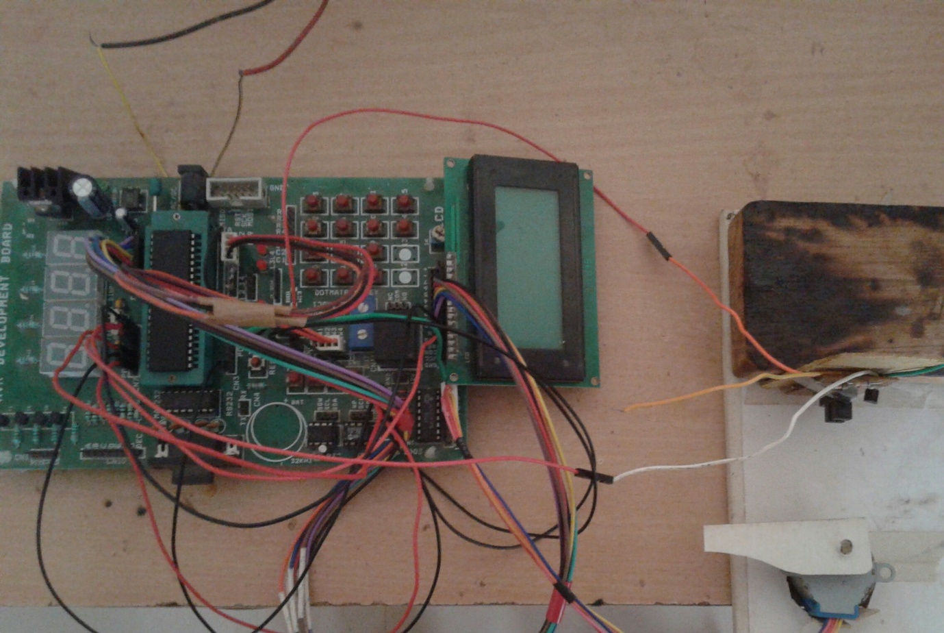
Fig. 1: Prototype of NE567 IC based Phase Locked Loop Circuit

Circuit operation:

The transmitter generates square wave and its frequency is varied by varying 1K pot. This square wave output is given as input to receiver that is working as PLL. It locks at one particular frequency and gives low output. When output goes low, the LED glows because it is connected in current sinking mode. The frequency of transmitter and lock frequency of PLL receiver depends upon RC timing components. And because we have used same values of R and C at both sides when value of 1 K pot matches with receivers 1 K resistance, the generated frequency and lock frequency also matches because of same equation

F = 1 / 1.1 RC

So the PLL locks and gives low output to blink LED.

Circuit Diagrams

Circuit-Diagram-NE567-IC-Based-Phase-Locked-Loop-Prototype

Project Video


Filed Under: Electronic Projects


Questions related to this article?
👉Ask and discuss on EDAboard.com and Electro-Tech-Online.com forums.


Tell Us What You Think!! Cancel reply

You must be logged in to post a comment.

HAVE A QUESTION?

Have a technical question about an article or other engineering questions? Check out our engineering forums EDABoard.com and Electro-Tech-Online.com where you can get those questions asked and answered by your peers!


Featured Tutorials

  • Introduction to Brain Waves & its Types (Part 1/13)
  • Understanding NeuroSky EEG Chip in Detail (Part 2/13)
  • Performing Experiments with Brainwaves (Part 3/13)
  • Amplification of EEG Signal and Interfacing with Arduino (Part 4/13)
  • Controlling Led brightness using Meditation and attention level (Part 5/13)
  • Control Motor’s Speed using Meditation and Attention Level of Brain (Part 6/13)

Stay Up To Date

Newsletter Signup

Sign up and receive our weekly newsletter for latest Tech articles, Electronics Projects, Tutorial series and other insightful tech content.

EE Training Center Classrooms

EE Classrooms

Recent Articles

  • What are the battery-selection criteria for low-power design?
  • Key factors to optimize power consumption in an embedded device
  • EdgeLock A5000 Secure Authenticator
  • How to interface a DS18B20 temperature sensor with MicroPython’s Onewire driver
  • Introduction to Brain Waves & its Types (Part 1/13)

Most Popular

5G 555 timer circuit 8051 ai Arduino atmega16 automotive avr bluetooth dc motor display Electronic Part Electronic Parts Fujitsu ic infineontechnologies integratedcircuit Intel IoT ir lcd led maximintegratedproducts microchip microchiptechnology Microchip Technology microcontroller microcontrollers mosfet motor powermanagement Raspberry Pi remote renesaselectronics renesaselectronicscorporation Research samsung semiconductor sensor software STMicroelectronics switch Technology vishayintertechnology wireless

RSS EDABOARD.com Discussions

  • Poly Spacing Effect
  • Thyristor Gate Drive
  • Passive Harmonics Filter
  • Variable Phase shift control circuit for PWM circuit
  • Avalanche Pulser

RSS Electro-Tech-Online.com Discussions

  • HV Diodes
  • Question about ultrasonic mist maker
  • Someone please explain how this BMS board is supposed to work?
  • DIY bluetooth speaker
  • Disabled son needs advice please
Engineers Garage
  • Analog IC TIps
  • Connector Tips
  • DesignFast
  • EDABoard Forums
  • EE World Online
  • Electro-Tech-Online Forums
  • Microcontroller Tips
  • Power Electronic Tips
  • Sensor Tips
  • Test and Measurement Tips
  • 5G Technology World
  • About Us
  • Contact Us
  • Advertise

Copyright © 2022 WTWH Media LLC. All Rights Reserved. The material on this site may not be reproduced, distributed, transmitted, cached or otherwise used, except with the prior written permission of WTWH Media
Privacy Policy | Advertising | About Us

Search Engineers Garage

  • Projects and Tutorials
    • Electronic Projects
      • 8051
      • Arduino
      • ARM
      • AVR
      • PIC
      • Raspberry pi
      • STM32
    • Tutorials
    • Circuit Design
    • Project Videos
    • Components
  • Articles
    • Tech Articles
    • Insight
    • Invention Stories
    • How to
    • What Is
  • News
    • Electronic Products News
    • DIY Reviews
    • Guest Post
  • Forums
    • EDABoard.com
    • Electro-Tech-Online
    • EG Forum Archive
  • Digi-Key Store
    • Cables, Wires
    • Connectors, Interconnect
    • Discrete
    • Electromechanical
    • Embedded Computers
    • Enclosures, Hardware, Office
    • Integrated Circuits (ICs)
    • Isolators
    • LED/Optoelectronics
    • Passive
    • Power, Circuit Protection
    • Programmers
    • RF, Wireless
    • Semiconductors
    • Sensors, Transducers
    • Test Products
    • Tools
  • EE Resources
    • DesignFast
    • LEAP Awards
    • Oscilloscope Product Finder
    • White Papers
    • Webinars
  • EE Learning Center
    • Design Guides
      • WiFi & the IOT Design Guide
      • Microcontrollers Design Guide
      • State of the Art Inductors Design Guide
  • Women in Engineering