Engineers Garage

  • Projects and Tutorials
    • Circuit Design
    • Electronic Projects
      • 8051
      • Arduino
      • ARM
      • AVR
      • PIC
      • Raspberry pi
      • STM32
    • Tutorials
    • Components
  • Articles
    • EG Blogs
    • Insight
    • Invention Stories
    • How to
    • What Is
    • News
      • EE Design News
      • DIY Reviews
      • Guest Post
      • Sponsored Content
  • Forums
    • EDABoard.com
    • Electro-Tech-Online
    • EG Forum Archive
  • Digi-Key Store
    • Cables, Wires
    • Connectors, Interconnect
    • Discrete
    • Electromechanical
    • Embedded Computers
    • Enclosures, Hardware, Office
    • Integrated Circuits (ICs)
    • Isolators
    • LED/Optoelectronics
    • Passive
    • Power, Circuit Protection
    • Programmers
    • RF, Wireless
    • Semiconductors
    • Sensors, Transducers
    • Test Products
    • Tools
  • EE Resources
    • DesignFast
    • LEAP Awards
    • Oscilloscope Product Finder
    • Video
    • White Papers
    • Webinars
  • EE Learning Center
  • Women in Engineering

Interfacing a Piezo Buzzer with Stm32 Microcontroller

June 6, 2019 By EG Projects

In this tutorial i am going to teach you how to interface a piezo buzzer with 32-bit stm32 microcontroller? It seems to be an easy project but proper circuit configuration and electrical concepts are critical to become a successful embedded hardware engineer. I will elaborate each component used in the project and why it is part of the circuit? Also i will explain about stm32 microcontroller software code flow. 

Stm32 Buzzer Alarm – Project functionality

The functionality of the project is simple. One push button and a piezo buzzer is part of the project. When ever a user presses the push button buzzer sound will propagate or buzzer starts ringing. Its seems to be simple logic but implementing it is little hard especially for the newbies.

Stm32 Buzzer Project main skill development

Power requirements, use of transistor and pull up/pull down resistors plays a vital role in implementing the correct logic. What i want to deliver through this project is what i wrote in the previous sentence.

Piezo Buzzer with Stm32 microcontroller – Main Project

Stm32f103c8t6 microcontroller is used in the tutorial. I used a pre-assembled cheap stm32f103c8t6 microcontroller development board in this tutorial. Pre-fabricated development boards are a great resource for development and testing the hardware in a short amount of time.  I always prefer to use them in tutorials.

I write a getting started with stm32f103c8t6 development board tutorial and you can find it by clicking the below button. Button will lead you to a tutorial which explains about the board and how to configure and program it using stm32cubemx software utility.

Getting started with Stm32c8t6 and Stm32cubemx

The above tutorial is very important you can easily understand the project code below if you take the tutorial. The important step covered in the above tutorial which is not explained in this tutorial is

  • How to configure the GPIO pins of stm32 microcontroller in stm32cubemx code configurator and how to import the code in keil uvison arm ide.

Stm32 Piezo Buzzer – Project Circuit

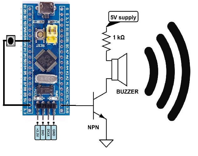
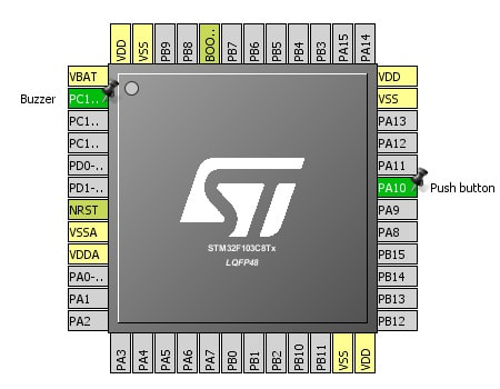
 Push button is connected to microcontroller Port-A pin#10. Buzzer alarm is controller through microcontroller Port-C pin#13. 

Why i used transistor in the circuit?
Well stm32 microcontrollers are 3.3 volt tolerant devices. Their GPIO’s can output max voltage of 3.3 v and source about 20 mA to 40 mA of current at 3.3 volts. This voltage and current is not suitable for driving a piezo buzzer.  Small piezo buzzers operates on 3-5v and consumes about 15 mA of current. Average piezo buzzers works on about 5 volts and consumes 50 mA of current. So its a bad idea to directly drive a piezo sound buzzer with stm32 microcontroller or any general purpose microprocessor GPIO pin. 

Transistor on the other hand operates on a very small voltage and have the ability to drive heavy loads which are not possible to drive directly with GPIO’s of microcontrollers. To prevent stm32 microcontroller from any power related issues like power on reset and other potential errors buzzer is interfaced with transistor.  Now transistor controls the buzzer and transistor is controlled by stm32 microcontroller.  

An NPN transistor is used in the project. Buzzer is connected to collector side of the npn transistor with a 1 k ohm resistor. Resistor limits the current drained by buzzer and only lets the needed amount by buzzer to flow in the circuit.

Buzzer with Stm32 Microcontroller

Buzzer with Stm32 Microcontroller

Pull up and pull down resistors activation

Stm32 microcontroller has built in pull up and pull down resistors associated with each gpio pins. We can activate or deactivate them when desired. By default they are in sleep mode we have to activate them if we want to use them in our circuit.

I activated resistors associated with each pin i used in the project. Push button is used as input. I activated its pull up resistor. One end of push button is connected to stm32 Port-A pin#10 and the other end is grounded. Pull up resistor is activated to normally make the input high. Now when ever the user presses the push button the input state changes from 5 volts to 0 volts and microcontroller will accept it as voltage transition and we can do our stuff when transition is recognized. I don’t want the input pin to be floating so i activated the pull up resistor. In code you can understand it easily. I will also explain it in code. Our input pin now behaves like the system below.   

Stm32 GPIO pull up resistor configuration

Stm32 GPIO pull up resistor configuration

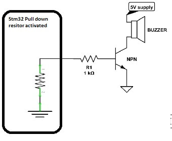
On output pin Port-C pin#13 i activated the pull down resistor. Why i activated it? At output of pin our NPN transistor base is connected. NPN transistor activates its channel when its base is made high. In our case we want to switch on the transistor when ever user presses the button. Normally we want the transistor to remain off. So instead to leave the transistor base floating its better to ground it. Ground it will ensure that the transistor will remain off when not in use. Our system will look some thing below. 
Picture

Stm32 microcontroller Pull down resistor activated

Buzzer with stm32 microcontroller – Project code

Stm32f103c8t6 is configured/initialed using stm32cubemx. I explained all the initialization steps in the tutorial which is recommend above. I hope you took the above tutorial and know how configuration is done in this project.   
Stm32 pins used in buzzer project - Stm32cubemx code configurator

Stm32 pins used in buzzer project – Stm32cubemx code configurator

Stm32 gpio’s pull up and pull down resistors are also activated through gpios configuration window in stm32cubemx. I activated the resistor below and named the microcntroller pins. You can see the gpio screen settings window below.   
Stm32cubemx buzzer and push button GPIO declaration

Stm32cubemx buzzer and push button GPIO declaration

The main logic of code is in while(1) loop. The statement below is checking if the button is pressed or not. Statement is monitoring if the pin is grounded. Grounded case is possible only if we press the push button.  
if(HAL_GPIO_ReadPin(Push_button_GPIO_Port, Push_button_Pin)==GPIO_PIN_RESET)  
If button pressed then make the Port-C pin#13 high. Normally port-c pin#13 is low due to pull down resistor activation. When the stm32 pin is made high it sources 3 volts out. Which ultimately makes the base of transistor high and transistor channel activates making buzzer to produce sound.  
HAL_GPIO_WritePin(Buzzer_GPIO_Port, Buzzer_Pin,GPIO_PIN_SET);               
If no press remain low. 
HAL_GPIO_WritePin(Buzzer_GPIO_Port, Buzzer_Pin,GPIO_PIN_RESET);             
 The above project is just to teach you how you can interface a buzzer with stm32 microcontroller. More advance projects involving buzzer and stm32 microcontroller are in pipe line. In coming months i will definitely make a home automation or security system project using buzzer alarm, stm32 microcontroller and other sensors. 

Future Work:
You can design an alarm using buzzer and clock with stm32 microcontroller. A security system involving buzzer and other actuators will be a nice project to take one step a head from this buzzer with stm32 getting started tutorial.     

Download the project code. Folder contains project files of stm32cubemx and keil uvision arm ide. Please provide us your feed back on the project. Write your comments and quires below.
Project files/code

Related Articles Read More >

A Bluetooth-controlled datalogger robot
touch bell push
How to design a touchless bell push using Arduino
SMS-enabled scrolling message board using Arduino
Interfacing stepper motor with 8051(89c51,89c52 ) microcontroller

Featured Tutorials

  • Screenshot of Raspbian OS on Raspberry Pi RPi Python Programming 03: Raspberry Pi as Linux System
  • Raspberry Pi Models RPI Python Programming 02: Raspberry Pi Models
  • Raspberry Pi 4 RPi Python Programming 01: Introduction to Raspberry Pi 4
  • RPi Python Programming 05: Introduction to Python
  • RPi Python programming 04 RPi Python programming 04: Setting up Raspberry Pi Linux computer
  • Python Basics RPi Python Programming 06: Python basics

Stay Up To Date

Newsletter Signup

EE Training Center Classrooms

“ee

“ee

“ee

“ee

Recent Articles

  • NXP launches its first Wi-Fi 6E Tri-Band system-on-chip
  • Nexperia launches industry’s first 80 V RETs for high-voltage bus circuits
  • TDK releases low-profile medical sensors
  • Getting started with Raspberry Pi
  • STMicroelectronics offers integrated RF front-end for global navigation satellite systems
...

RSS EDABOARD.com Discussions

  • Power controll on 230V with zero switching and PWM?
  • FT232 > Package
  • ADS EM simulation
  • Deviation of dain current of PA between simulation and measurement
  • multi-voltage synthesis problem

RSS Electro-Tech-Online.com Discussions

  • new to Ardunio but trying to compile
  • Jon's Imaginarium – A Comment
  • Where can I find a pole pig?
  • NE555p circuit help
  • Where has the fun gone?
Engineers Garage
  • Analog IC TIps
  • Connector Tips
  • DesignFast
  • EDABoard Forums
  • EE World Online
  • Electro-Tech-Online Forums
  • Microcontroller Tips
  • Power Electronic Tips
  • Sensor Tips
  • Test and Measurement Tips
  • 5G Technology World
  • About Us
  • Contact Us
  • Advertise

Copyright © 2021 WTWH Media LLC. All Rights Reserved. The material on this site may not be reproduced, distributed, transmitted, cached or otherwise used, except with the prior written permission of WTWH Media
Privacy Policy | Advertising | About Us

Search Engineers Garage

  • Projects and Tutorials
    • Circuit Design
    • Electronic Projects
      • 8051
      • Arduino
      • ARM
      • AVR
      • PIC
      • Raspberry pi
      • STM32
    • Tutorials
    • Components
  • Articles
    • EG Blogs
    • Insight
    • Invention Stories
    • How to
    • What Is
    • News
      • EE Design News
      • DIY Reviews
      • Guest Post
      • Sponsored Content
  • Forums
    • EDABoard.com
    • Electro-Tech-Online
    • EG Forum Archive
  • Digi-Key Store
    • Cables, Wires
    • Connectors, Interconnect
    • Discrete
    • Electromechanical
    • Embedded Computers
    • Enclosures, Hardware, Office
    • Integrated Circuits (ICs)
    • Isolators
    • LED/Optoelectronics
    • Passive
    • Power, Circuit Protection
    • Programmers
    • RF, Wireless
    • Semiconductors
    • Sensors, Transducers
    • Test Products
    • Tools
  • EE Resources
    • DesignFast
    • LEAP Awards
    • Oscilloscope Product Finder
    • Video
    • White Papers
    • Webinars
  • EE Learning Center
  • Women in Engineering