Here I present 3 in 1 parameter monitoring system. Means it measures and displays.
1. Current temperature (in oC )
2. Humidity (RH in %)
3. Light intensity (in %)
The interesting thing is it has digital cum analog meter console. Means values are displayed on LCD as a digital read out as well as they are indicated on the retro-styleanalog dial (scale). All three parameters are measured one by one and they are displayed on LCD as well as on analog dial after some delay. It continuously monitors all three parameters and displays them turn by turn on both meters.
The project is build using Arduino UNO board with DHT sensor (to measure temperature and humidity), LDR (to measure light intensity) and LCD. It uses servo motor as a pointer to indicate the value on an analog meter.

Fig. 1: Prototype of Arduino based 3-in-1 Digital Cum Analog Parameter Monitor
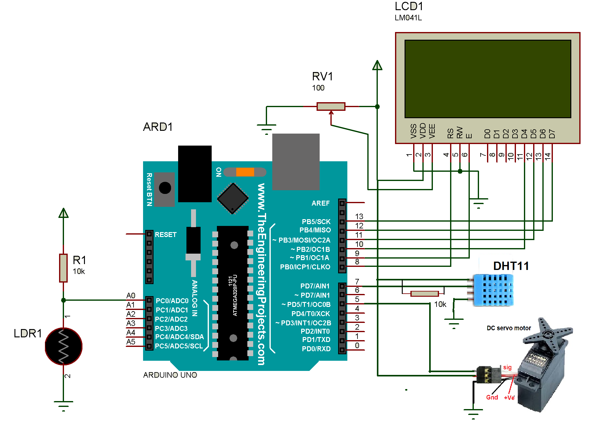
CIRCUIT DESCRIPTION
1. The output of DHT11 pin 2 is connected to digital pin 7 or Arduino board. The pin is also pulled high by 10 K resistor. Pin 1 of DHT11 is given +5 V supply from Arduino board and pin 4 is connected to ground. Pin 3 is left unconnected.
2. LCD control pins Rs and En are connected to Arduino pins 8 and 9 respectively. One more control pin RW is connected to ground to make LCD write enable.
3. LCD data pins D4 – D7 are connected to Arduino pins 10 – 13
4. One pot of 10K is connected to LCD to vary its contras on Vee pin. LCD backlight terminals LED+ and LED- are connected to 5V and ground respectively.
5. One LDR is connected in pull UP configuration with 10 K pull up and its output is given to analog input pin A0 of arduino as shown.
6. Finally, the analog output pin 5 drives servo motor. This pin is connected to servo motor’s signal input.
7. Servo motor, LCD, and LDR all are given 5V supply through the board.

Fig. 2: Image of Arduino based 3-in-1 Digital Cum Analog Parameter Monitor
CIRCUIT OPERATION
• The arduino first reads temperature from DHT11 sensor and displays its value on LCD
• At the same time, it also displays the temperature on an analog scale between 0 – 100oC. The servo motor can rotate maximum to 180o. So to display 0 to 100oC on 0 to 180o scale, the motor is rotated to an angle = temperature value x 1.8. as the motor rotates to the desired degree, the pointer attached to motor shaft points to temperature value on the analog dial (scale)
• The temperature value is displayed on both analog cum digital meter for 5 second
• After 5 seconds, the arduino reads humidity value from DHT11 sensor and displays it on LCD
• Again, at the same time, the humidity is also displayed on the analog scale as 0 – 100%. Similar to the temperature reading, the RH reading is also multiplied by 1.8 and servo motor is rotated to an angle = RH reading x 1.8. The pointer scale points to RH% on same analog dial
• Humidity value is also displayed on both meters for 5 second
• Next, arduino reads analog voltage at pin A0 from LDR. As we know the LDR resistance varies as light intensity varies and due to that the analog output voltage from LDR also varies. This voltage is first converted into a digital value between 0 to 1023 for 0 to 5 volt (means when light intensity is less or minimum the LDR output is very less around 0V. so the digital output will be also 0. But as light intensity increases, the LDR output increases upto 5V and corresponding digital output also increases upto 1023). The 0 to 1023 range is squeezed (transformed) into 0 to 100% of light intensity
• Now as light intensity varies – the analog output of LDR varies – the digital value varies – and this value is displayed on LCD as 0 to 100% of light intensity
• Again this 0 to 100% of light intensity is displayed on analog dial same as previous two parameters
• The light intensity value is also displayed for 5 second
• Again the cycle repeats of temperature – humidity – light intensity – temperature.
Thus all three parameter values temperature, humidity, and light intensity are displayed on both digital as well as analog scale.
SOFTWARE PROGRAM
Complete functionality of project is because of the program downloaded into arduino board microcontroller ATMega328. The program is the soul of the project. The program (also known as sketch) is written and compiled in arduino IDE software tool. And it is burned (embedded) into ATMega328 using built in software programmer tool AVRISP MK-II through the USB port.
Project Source Code
###
#include <LiquidCrystal.h> #include <Servo.h> #include "DHT.h" #define DHTPIN 7 #define DHTTYPE DHT11 LiquidCrystal lcd(8, 9, 10, 11, 12, 13); DHT dht(DHTPIN, DHTTYPE); Servo servo1; void setup() { servo1.attach(5); servo1.write(0); lcd.begin(16,4); lcd.clear(); dht.begin(); delay(5000); } void loop() { int motor_angle; int light = analogRead(A0); float rh = dht.readHumidity(); float temp = dht.readTemperature(); light = map(light,0,1023,0,100); lcd.clear(); lcd.print("temperature:"); lcd.setCursor(0,1); lcd.print(temp); lcd.print(" C"); motor_angle = temp*1.8; servo1.write(motor_angle); delay(5000); lcd.clear(); lcd.print("Humidity:"); lcd.setCursor(0,1); lcd.print(rh); lcd.print(" % RH"); motor_angle = rh*1.8; servo1.write(motor_angle); delay(5000); lcd.clear(); lcd.print("Light intensity:"); lcd.setCursor(0,1); lcd.print(light); lcd.print(" %"); motor_angle = light*1.8; servo1.write(motor_angle); delay(5000); }###
Circuit Diagrams
Project Video
Filed Under: Electronic Projects
Filed Under: Electronic Projects

Questions related to this article?
👉Ask and discuss on Electro-Tech-Online.com and EDAboard.com forums.
Tell Us What You Think!!
You must be logged in to post a comment.