If you are newbie and don’t know about internal structure of character lcd and how to interface it with microcontrollers? Than i suggest you you first take the getting started with lcd tutorial.
As you know first we have to initialize the lcd that we are using (8×1, 8×2, 8×4, 16×1, 16×2, 16×4, 20×1, 20×2, 20×4, 24×1, 24×2, 24×4, 32×1, 32×2, 40×1, 40×2, 40×4). By initialization I mean
- Should the cursor appears on lcd or not? If appearing, whether it should be blinking or normal?
- What should be the size of character-font appearing on lcd (5×8, 5×10)?
To learn about lcd initialization standard commands go through the simple tutorial below.
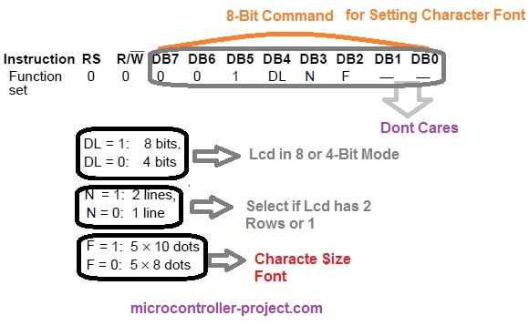
We are going to discuss only commands that are related to character size Font-matrix in this tutorial. To initialize character lcd we have to send commands to command-register of lcd. All the commands are 8-bit in nature. For Initializing character font size, 8-bit commands individual bits represents.
- DL selects lcd mode. 8-bit or 4-bit. Don’t know Go through the tutorial(Lcd in 4-bit and 8-bit mode)
- N selects if lcd contains 2 rows or 1.
- F selects character font size. (5×8 or 5×10)
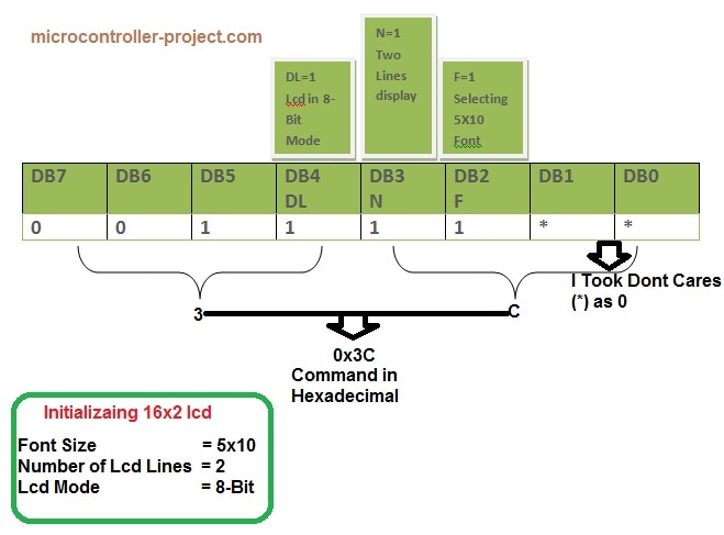
Now if I have a 16×2 lcd and i want to initialize its Character font to be 5×10 my command will be.
Standard Lcd Commands for 5×10 Display
- You can display 208 characters in 5×8 font and 32 characters in 5×10 font. Total ASCII characters present in HD44780 lcd controller are 240. In which 208 are in 5×8 font and 32 are in 5×10 font.
- In CG-RAM you can create 8 custom characters at a time in 5×8 font and 4 custom characters in 5×10 font. Don’t know about CG-RAM and custom characters? Go through(CG-RAM & custom characters generation and display)
See the difference in the same characters in same row, marked against red and green star. red star represents 5×8 font size character and green represents same character with 5×10 size font. Picture taken from hd44780 controller data sheet.
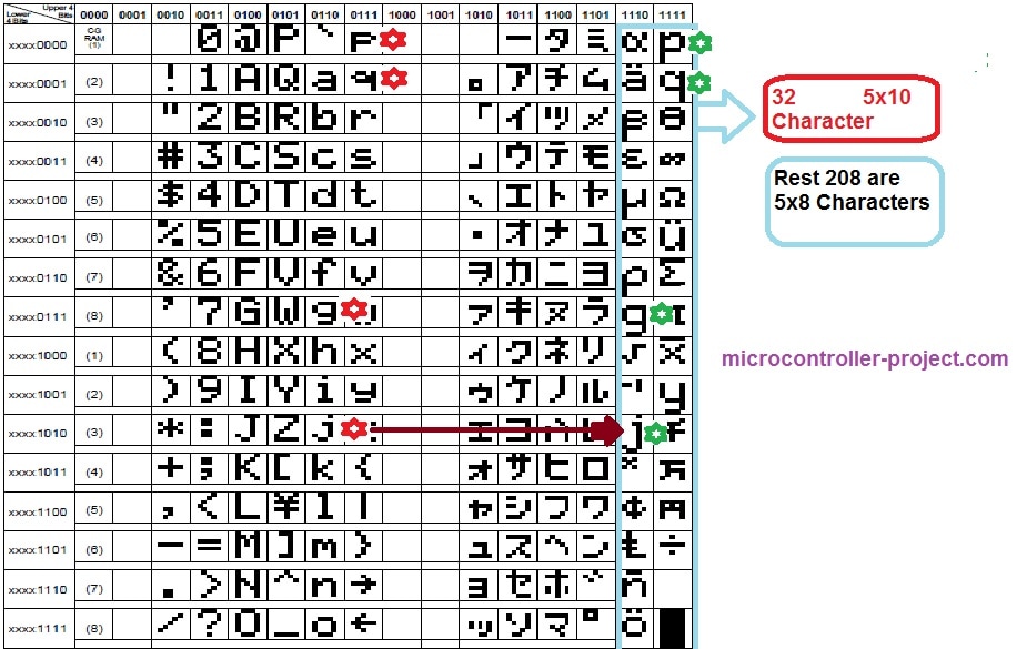 lcd 5×8 and 5×10 size characters present in hd44780 controller ascii set
Displaying 5×10, 5×8 font size Characters on character lcd Using PIC16f877 Microcontroller.
- PIC 16f877 microcontroller
- 16×2 lcd
- Potentiometer (To set Lcd Contrast)
- Crystal (20 MHz)
- Capacitors 33Pf
I am going to print/display G,J,P & Q in 5×8 and 5×10 font. These characters are present in HD44780 Controller in 5×8 and 5×10 font. I will call their addresses and they will appear/display on lcd screen.
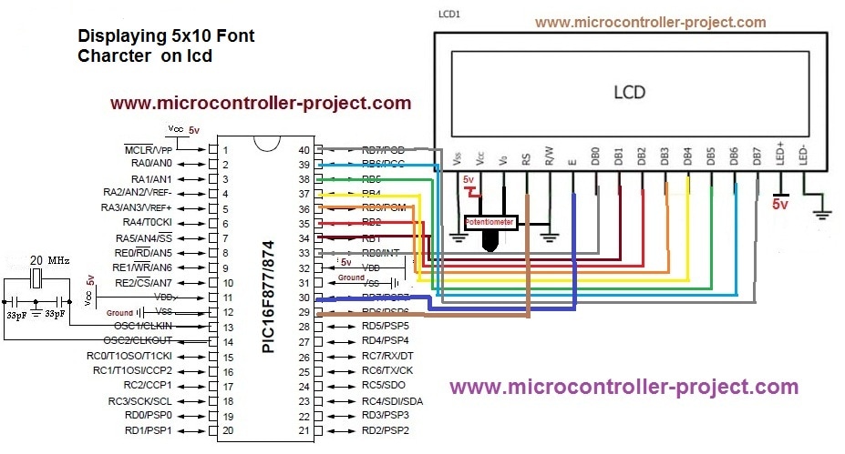
Lcd data pins are Connected to Port-B of microcontroller. Lcd control pins (en,rs,rw) are connected to Port-D Pins#7,6,5. Rest of the connections are normal connections. Supplying power to microcontroller. Grounding GND pin. Connecting Crystal to microcontroller etc. Circuit diagram of the project is given below.
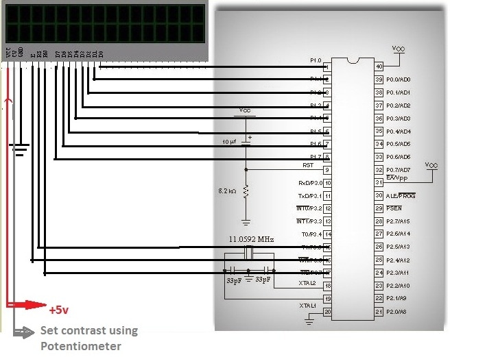
Displaying 5×10, 5×8 Characters on 16×2 lcd Using 8051(89c51, 89c52) Microcontroller.
- 8051(89c51,89c52) series microcontroller
- 16×2 lcd
- Potentiometer (To set Lcd Contrast)
- Crystal (11.0592 MHz)
- Capacitors 33Pf
Lcd data pins are connected to Port-1 of microcontroller. Lcd controlling pins en,rs,rw are connected to Port-3 pins#5,6,7. Circuit diagram of the project is given below.
Filed Under: Microcontroller Projects, PIC Microcontroller.



Questions related to this article?
👉Ask and discuss on Electro-Tech-Online.com and EDAboard.com forums.
Tell Us What You Think!!
You must be logged in to post a comment.