Musical RGB LED chaser using AT89C52
Many of you may have seen different kinds of LED chasers, single colour LED chaser, multi colour LED chaser, propeller LED chaser, multiple parallel LED chaser etc. But here, the given LED chaser is different than all these kinds of LED chaser because it consists of RGB LEDs. Not only that but it has musical sound output also. RGB LED is a special kind of LED which can glow in three different colours – RED, GREEN and BLUE. So in single LED you will get three different colours. There is common anode type or common cathode type RGB LED. In common anode type RGB LED there is only one anode but there are 3 cathodes – one for RED colour, second for GREEN and third for BLUE. In common cathode type, there are three anodes for RED – GREEN and BLUE colours and only one cathode.
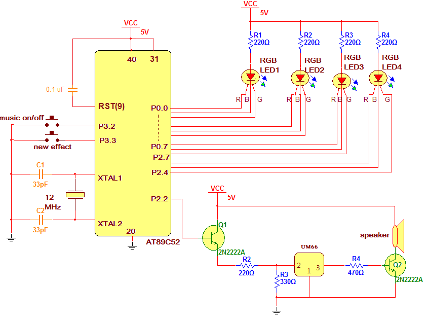
The given project generates various multicolour chasing effects using 4 common anode type RGB LEDs using micro controller AT89C52. It also consists of melody generator chip UM66 to generate nice melody sound in tune with this multicolour chasing effect. The project demonstrates five eye-catching chasing effects with only 4 RGB LEDs but one can generate as many as 100’s of chasing effects with at most 10 RGB LEDs (each LED needs at least 3 lines so 10 LEDs requires 30 lines and AT89C52 has a maximum of 32 IO lines). Also one can increase the number of LEDs by connecting them in parallel and using current driver chip ULN2083.
So finds it interesting? Do you want to build the project and know how this can be done? Let us start. First see the circuit diagram and afterwards see the description and operation. The software program is given at the end.
Description:
The circuit consist of microcontroller AT89C52, four RGB LEDs, melody generator chip UM66 and few other components like transistors, resistors, capacitors and crystal.
· Two push buttons are connected to port 3 pins P3.2 (12) and P3.3(13) that generates external interrupt EXT0 and EXT1 when pressed.
· A 12 MHz crystal is connected to XTAL1 (18) and XTAL2 (19) pins along with two 33 pF capacitors. It provides a basic clock signal to the microcontroller.
· A 0.1 µF capacitor is connected between Vcc and RST (9) pin to provide power on reset signal.
· EA (31) pin is connected to Vcc to enable internal memory enable and make the program run from internal FLASH.
· Four common anode type RGB LEDs are connected to port P0 and P2 as shown. The anodes of all four LEDs are connected to Vcc through current limiting resistors. Three cathodes of each LEDs total 12 are connected to P0 pins P0.0 – P0.7 and P2 pins P2.7 – P2.4 in sequence as R-B-G-R-B-G-…….
· Pin P2.2 drives input of UM66 chip through transistor Q1 and voltage divider network consist of R2 and R3. The transistor amplifies the current output of micro controller pin and voltage divider network limits input voltage to around 3 V.
· The output of UM66 drives 8Ω@10W speaker through another transistor Q2.
Operation:
· When power is given to circuit music and all RGB LEDs are off
· When music on/off button is pressed it will generate an interrupt. On getting an interrupt micro controller will send high output on pin P2.2 pin so transistor Q1 will conduct and UM66 gets high input. So it will generate melody sound through the speaker.
· When music on/off button is pressed again, on getting interrupt second time, micro controller will send low output to pin P2.2. So music will be off. Thus as the button is pressed every odd times the music is ON and when the button is pressed even times, music will be OFF.
· Next to start LED chasing effect, new effect button is pressed. As the button is pressed, it will generate an interrupt and that will start new chasing effect. There are five different chasing effects.
· When button is pressed 1st time, it will start 1st effect. In this effect one by one all LED will blink with RED colour then with blue colour and then with green colour and they continue to blink in this sequence like R – R – R – R – B – B – B – B – G – G – G – G – R – ……. likewise. Chasing effect continue till button is not pressed.
· As the button is pressed again, the next 2nd chasing effect will start. In this effect at a time two LEDs blinks – LED1 and LED3 blinks with same colour and LED2 and LED4 blinks with some different colour. In this effect there are three sequences. In 1st sequence LED1 & LED3 blinks with RED colour and LED2 & LED4 blinks with GREEN colour for 25 times. In 2nd sequence LED1 & LED3 blinks with BLUE colour and LED2 & LED4 blinks with RED colour for 25 times. And in last 3rd sequence LED1 & LED3 blinks with GREEN colour and LED2 & LED4 blinks with BLUE colour for 25 times. All above 3 sequences continue till new effect buttons is not pressed again.
· When button is pressed again 3 chasing effect will start. In this effect one by one LEDs will turn ON (not just only blink) from left to right and right to left with different colours. First all LEDs will turn ON in RED colour from left to right. Then all the LEDs will turn ON in green colour from right to left. Again all the LEDs will turn ON in blue colour from left to right and finely all the LEDs will turn ON with white colour from right to left. The cycle continuous.
· To start next 4th chasing effect new effect buttons is pressed again. In this effect each LED will turn ON with different colour every time. First LED1 glows RED, LED2 glows BLUE, LED3 glows GREEN and LED4 glows WHITE. Then LED1 glows BLUE, LED2 glows GREEN, LED3 glows WHITE and LED4 glows RED. Likewise the sequence is RBGW – BGWR – GWRB – WRBG – RBGW – …… and so on.
· When button is pressed one more time the last chasing effect is colour changing of LEDs with fading. The brightness of LEDs are varied from min to max as well as their colours are also changed. The brightness of LED1 & LED3 is decreased and at the same time brightness of LED2 and LED4 are increased and vice versa. Their colours are also changed from RED to BLUE and BLUE to GREEN.
· As anyone keeps on pressing new effect button these 5 chasing effects will be repeated.
Software program:
The software program is responsible for the complete operation of the circuit. The program is loaded into internal FLASH of AT89C52. The software program is very simple and easy. It is written in C language. It is compiled using KEIL cross compiler.
Project Source Code
###
#include <reg51.h>
#include<intrins.h>
#define ON 1
#define OFF 0
sbit music_op = P3^0;
unsigned int new_effect_flag=0,int1_count=0,int0_count=0;
void delay()
{
unsigned int x,y;
for(x=0;x<50;x++)
for(y=0;y<1000;y++);
}
void delay2(int z)
{
unsigned int w;
for(w=0;w<z;w++)
{_nop_();_nop_();}
}
void ext_int_1_ISR() interrupt 2
{
delay();
int1_count++;
if(int1_count==6) int1_count=1;
new_effect_flag=1;
}
void ext_int_0_ISR() interrupt 0
{
delay();
int0_count++;
if((int0_count)%2==0) music_op = ON;
else music_op = OFF;
}
void effect1()
{
new_effect_flag=0;
while(new_effect_flag==0)
{
P0 = 0xFE;
P2 = 0xF0;
delay();
P0 = 0xF7;
delay();
P0 = 0xBF;
delay();
P0 = 0xFF;
P2 = 0xB0;
delay();
P0 = 0xFD;
P2 = 0xF0;
delay();
P0 = 0xEF;
delay();
P0 = 0x7F;
delay();
P0 = 0xFF;
P2 = 0xD0;
delay();
P0 = 0xFB;
P2 = 0xF0;
delay();
P0 = 0xDF;
delay();
P0 = 0xFF;
P2 = 0x70;
delay();
P2 = 0xE0;
delay();
}
}
void effect2()
{
int a;
new_effect_flag=0;
while(new_effect_flag==0)
{
for(a=0;a<25;a++)
{
P0 = 0xBE;
P2 = 0xF0;
delay();
P0 = 0xDF;
P2 = 0xE0;
delay();
if(new_effect_flag==1) break;
}
for(a=0;a<25;a++)
{
P0 = 0xFB;
P2 = 0x70;
delay();
P0 = 0xEF;
P2 = 0xD0;
delay();
if(new_effect_flag==1) break;
}
for(a=0;a<25;a++)
{
P0 = 0x7D;
P2 = 0xF0;
delay();
P0 = 0xF7;
P2 = 0xB0;
delay();
if(new_effect_flag==1) break;
}
}
}
void effect3()
{
new_effect_flag=0;
while(new_effect_flag==0)
{
P0 = 0xFE;
P2 = 0xF0;
delay();
P0 = 0xF6;
delay();
P0 = 0xB6;
delay();
P2 = 0xB0;
delay();
P2 = 0xE0;
P0 = 0xFF;
delay();
P2 = 0x60;
delay();
P0 = 0xDF;
delay();
P0 = 0xDB;
delay();
P0 = 0xFD;
P2 = 0xF0;
delay();
P0 = 0xED;
delay();
P0 = 0x6D;
delay();
P2 = 0xD0;
delay();
P2 = 0xC0;
P0 = 0xFF;
delay();
P2 = 0x40;
P0 = 0x7F;
delay();
P0 = 0x4F;
delay();
P0 = 0x49;
delay();
}
}
void effect4()
{
new_effect_flag=0;
while(new_effect_flag==0)
{
P0 = 0xFE;
P2 = 0xF0;
delay();
P0 = 0xEE;
delay();
P2 = 0x70;
delay();
P2 = 0x40;
delay();
P2 = 0xF0;
P0 = 0xFD;
delay();
P0 = 0xDD;
delay();
P0 = 0x5D;
P2 = 0x70;
delay();
P2 = 0x30;
delay();
P0 = 0xFB;
P2 = 0xF0;
delay();
P0 = 0xCB;
delay();
P0 = 0x8B;
delay();
P2 = 0xD0;
delay();
P2 = 0xF0;
P0 = 0xF9;
delay();
P0 = 0xF1;
delay();
P0 = 0x71;
delay();
P2 = 0xE0;
delay();
}
}
void effect5()
{
unsigned int a,b,a1;
new_effect_flag=0;
while(new_effect_flag==0)
{
for(a=10;a<100;a++)
{
a1 = 100-a;
for(b=0;b<10;b++)
{
P0 = 0xBE;
P2 = 0xF0;
delay2(a);
P0 = 0xDF;
P2 = 0xE0;
delay2(a1);
if(new_effect_flag==1) break;
}
}
for(a=99;a>10;a--)
{
a1 = 100-a;
for(b=0;b<10;b++)
{
P0 = 0xFB;
P2 = 0x70;
delay2(a);
P0 = 0xEF;
P2 = 0xD0;
delay2(a1);
if(new_effect_flag==1) break;
}
}
}
}
void main()
{
P0= 0x00;
P2=0x00;
music_op = 0;
P0 = 0xFF;
P2 = 0xFF;
IE = 0x85;
while(1)
{
P0 = 0xFF;
P2 = 0xF0;
switch(int1_count)
{
case 1:
effect1();
break;
case 2:
effect2();
break;
case 3:
effect3();
break;
case 4:
effect4();
break;
case 5:
effect5();
break;
}
}
}
###
Circuit Diagrams
Project Video
Filed Under: Electronic Projects
Filed Under: Electronic Projects

Questions related to this article?
👉Ask and discuss on Electro-Tech-Online.com and EDAboard.com forums.
Tell Us What You Think!!
You must be logged in to post a comment.