Light intensity meter using AT89C52 microcontroller
We all know that LDR (light dependent resistor) can be used as one of the most suitable light intensity detector because of its working principle. It works on the principle of photoconductivity. It’s made up of such material whose conductivity varies as per light falls on it. As more light falls on it, more number of photon strikes. The kinetic energy of photons is given to electrons – that makes more number of free electrons – that leads to increase in conductivity of the device. Thus as light intensity increases, the conductivity increases (resistance decreases) and vice versa. So the change is the resistance of LDR can be a measurement of the amount of falling light.
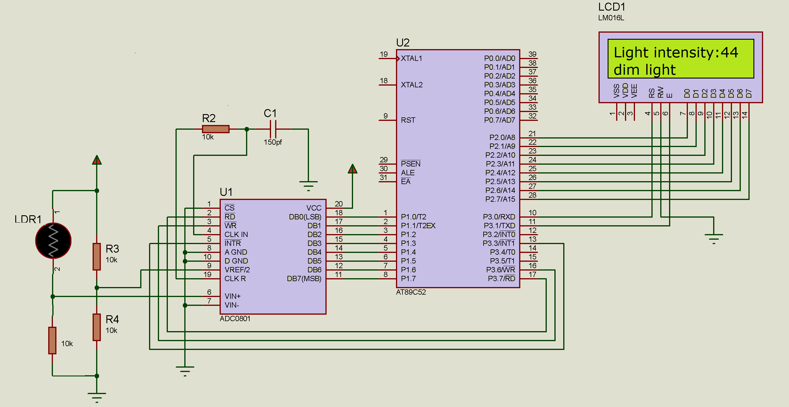
In the given project, LDR is used to measure light intensity inside the room. With a minor change in the circuit, it can be used to measure outdoor light intensity also. It uses microcontroller AT89C52 and LCD to display light intensity. It also indicates how much light inside room like “full light”, “good light”, dim light” etc. However, microcontroller cannot detect the change in resistance directly. LDR has to be given biasing voltage along with pull up or pull down resistance so that change in resistance is converted into change in voltage. The change in analog voltage is converted into digital equivalent using ADC and this digital value is read by microcontroller. Let us discuss this in somewhat more detail manner.
As shown in the figure to vary the voltage as per the change in light intensity and the resistance of LDR, the LDR can be connected with fixed value biasing resistance in pull up configuration or pull down configuration. If it is connected in the pull down configuration the voltage increases as light intensity increases and if it is connected in the pull up configuration the reverse will happen. How? Let us see.

Fig. 1: Circuit Diagram of LDR based Voltage Divider Networks used as Light Sensors
As shown in figure (a) the voltage at the junction of LDR and R (fix value resistance) V is
V = (R / R + LDR) × Vcc
So as LDR resistance decreases – means light increases, the voltage increases, and vice versa
In figure (b) the voltage equation changes to
V = (LDR / R + LDR) × Vcc
So in this connection as LDR resistance increases- means light decreases, the voltage increases, and vice versa. So we cannot use this second configuration because we want an increase in voltage with the increase in light intensity. In this project, LDR is used with pull down resistance configuration. Also, the value of fixed resistance R should be chosen after calculations such that as the LDR resistance varies from darkness to full light the voltage V should change from 0 to 5 V. It is very easy to find this value. Just measure the value of LDR resistance in darkness and full light and select the value of R as the mid value of this range. E.g. if LDR resistance varies from 1 K to 25 K (in full light to darkness) select R as 10 K.
So ready to build the project? Here is the circuit diagram followed by description and operation. Software program and logic explanation are given afterward.
Description:
· LDR is connected between Vcc supply and ground through a 10K resistor that gives it bias. The voltage across biasing resistance is given as analog input to ADC0801
· Digital outputs DB0 – DB7 are connected to port P1 of AT89C52 microcontroller
· Control pins RD and WR of ADC are connected with port P3 pins P3.7 and P3.6 respectively
· Interrupt output pin INTR from ADC is connected to external interrupt 1 pin INT1
· Chip select pin CS is connected to ground to make chip always enable
· RC components are connected to CLK R and CLK IN pins that provides internal clock to ADC
· VREF/2 pin is given voltage through potential divider of R3 and R4
· The LCD data pins D0-D7 are connected to port P2. Control pins RS and En are connected with port P3 pins P3.0 and P3.1 respectively. RW pin is connected to ground to enable LCD write always enable
· 1K Pot (not shown in the circuit) is connected to VEE pin to vary brightness of LCD
· A 12 MHz crystal is connected to crystal input pins XTAL1 and XTAL2 along with two capacitors (not shown in the figure). It generates required clock signal for the microcontroller.
Circuit operation:
When light falls on LDR, its resistances varies. More the light falls on LDR decrease its resistances. As the LDR resistance decreases the analog input voltage to ADC increases. That means the input voltage to ADC is directly proportional to light intensity falling on LDR. So more light more voltage and less light less voltage.
ADC converts this analog voltage into 8-bit digital value and gives it to the microcontroller. Microcontroller gets this binary input converts it into decimal and displays it on LCD as light intensity. As the voltage varies from 0 V to around 4.5 V the corresponding digital output varies from 0 to maximum 240 – 250. The maximum value is 255 because of its 8 bit ADC.
The microcontroller compares this value with a different range of values and decides how much light intensity is. If light intensity value is less than 50 then its very low light so microcontroller displays message “dim light”. Likewise, as the value increases the microcontroller decides whether its medium light, good light or full light etc. Please refer the following table:
|
Sr no |
Range of light intensity value |
decision |
|
1 |
0 – 50 |
Dim or very low light |
|
2 |
50 – 100 |
Medium light |
|
3 |
100 – 200 |
Good light |
|
4 |
More than 200 |
Full light |
Software program and logic:
The program downloaded into internal FLASH of AT89C52 is the soul of the project. It performs following functions
· Handles LCD
· Handles ADC
· Converts HEX value into decimal and then decimal into ASCII
· Compares light intensity value and decides how much light
So it’s actually the program that gives all the required functionalities to the project. The program is written in C language. It is compiled using KEIL (IDE) cross compiler. Here is the complete C program.
Project Source Code
###
#include<reg51.h>
#include <string.h>
sbit wr = P3^6;
sbit rd = P3^7;
sbit rs = P3^0;
sbit en = P3^1;
unsigned char d=0x00;
unsigned int prev_value=0,new_value;
void delay()
{
int p,q;
for(p=0;p<250;p++)
for(q=0;q<1000;q++);
}
void lcddly()
{
int x;
for(x=0;x<1500;x++);
}
void writecmd(unsigned char a)
{
lcddly();
rs = 0;
P2 = a;
en = 1;
en = 0;
}
void writedat(unsigned char b)
{
lcddly();
rs = 1;
P2 = b;
en = 1;
en = 0;
}
void writestr(unsigned char *s)
{
unsigned char l,i;
l = strlen(s);
for(i=0;i<l;i++)
{
writedat(*s);
s++;
}
}
void init_lcd()
{
writecmd(0x3C);
writecmd(0x0F);
writecmd(0x01);
writestr(" light intensity");
writecmd(0xC0);
writestr(" detector");
delay();
}
void int1(void) interrupt 2
{
rd = 0;
d=P1;
rd=1;
}
void display_light_intensity()
{
unsigned int tmp1,tmp2,t1,t,j;
unsigned char asci[3];
tmp1 = (d & 0x0F);
tmp2 = d & 0xF0;
tmp2 = tmp2>>4;
t = tmp1+tmp2*16;
new_value = t;
if(new_value != prev_value)
{
if(t>=100)
{
t1=t%10;
asci[2]=t1+0x30;
t=t/10;
t1=t%10;
asci[1]=t1+0x30;
t = t/10;
asci[0] = t+0x30;
}
else
{
t1=t%10;
asci[1]=t1+0x30;
t=t/10;
asci[0]=t+0x30;
asci[2] = 0x20;
}
writecmd(0xC0);
for(j=0;j<=2;j++)
writedat(asci[j]);
writecmd(0x94);
if(d<50) writestr("-dim light ");
else if((d>=50) & (d<100))writestr("-midium light ");
else if((d>=100) & (d<200)) writestr("-good light ");
else if(d>=200) writestr("-full light ");
}
prev_value = new_value;
}
void initialize()
{
P1=0xFF;
P2=0x00;
P0 = 0x00;
P3=0x08;
wr = 1;
rd = 1;
IE=0x84;
}
void main()
{
initialize();
init_lcd();
writecmd(0x01);
writestr("light intensity=");
while(1)
{
wr=0;
wr=1;
while(d==0x00);
display_light_intensity();
delay();
d = 0x00;
}
}
###
Circuit Diagrams
Project Video
Filed Under: Electronic Projects
Filed Under: Electronic Projects

Questions related to this article?
👉Ask and discuss on EDAboard.com and Electro-Tech-Online.com forums.
Tell Us What You Think!!
You must be logged in to post a comment.