As today world completely depends on the power saving, this prototype will help to decrease the power consumption. Here we are using this circuit to control AC 60W bulb using 8-bit microcontroller and we are using the concept of pwm (pulse width modulation) technique to control the 60W load by which we can decrease the light intensity and thus power consumption of the load indirectly got decreased.
The concept is very low such as to decrease the intensity I need to decrease the voltage of AC input. Here we are using a controlling part which consists of a TRIAC to control the AC voltage and also other feature is controlling the frequency of the signal. It is clear that we need to control two parameters:
1) Frequency of the signal, and
2) Voltage of the signal.
As controller has timer peripheral by which we can control the frequency and using by PWM technique we can control the respected voltage of the load. Here we are also using zero crossing detection technique and interrupt peripheral of the controller to control the frequency.
To demonstrate the project we are connecting a load controllable circuit to the microcontroller and providing the intensity levels of the light using PC by UART protocol via MAX232.

Fig. 1: Prototype of AVR ATMega32 based AC Power Controller
Description:
Represent circuit in a simplified block diagram:

Fig. 2: Block Diagram of AVR ATMega32 based AC Power Controller
Explain working of each block including specific calculations:
Full wave rectifier:
· As here we are using full wave rectifier, peak voltage:

Fig. 3: Formulae for Root Mean Square Voltage
V rms=16.974V
· To get 5V from this we are using 7805 regulator in series for power supply.

Fig. 4: Circuit Diagram of Zero Crossing Detector
Zero crossing detection:
· As we need to control the sine wave here we are using zero crossing detection circuit which consists of optocoupler as we need to provide this 16V to microcontroller which works at low voltage 5V.
· Here we are generating the pwm of 1/50hz time period using TIMER2.
· In the above figure we can see the zero crossing detection and full wave rectification circuit.
AC Controller:
· Here this MOC3051 can control the signal voltage transmitting from the mocirocontroller to the TRIAC which isolates the AC and DC supply.

Fig. 5: Circuit Diagram of MOC3051 IC based AC Voltage Controller
Max 232 Board:
Max 232 board is useful for voltage conversion i.e., to convert from 5V to 12V and 12V to 5V, as PC works at 12V and controller works at 5V and need to share the data between them we use an interfacing medium such as MAX232 converter.

Fig. 6: Typical Image of Max232 Board
And here in this application if we keenly observe we have a DC GND and PC has digital GND, to make isolation of these two we use MCT2e NPN optocoupler.
IDE details:
Here we are using AVR multi programmer to dump the code written in AVR studio 5.0 IDE. And here we I have developed my own PCB using ARES software provided by the Labcenter electronics, as I had trial version.
We have used a Toner transfer method for developing the PCB at our home. Using FeCl3 solution as a chemical.

Fig. 7: Typical Image of AVR Multiprogrammer
Using this AVR multi programmer we can flash all AVR controllers.
Here we can use any third party programmers for flashing Atmega32 as it has inbuilt ISP programming functionality.
ISP programmer:
As given by the vendor we are using PROISP font end to dump the flash to the ATmega32.
Circuit Diagram and Implementation
Circuit diagram:
Circuits are shown in Circuit Diagram tab 1 and 2, respectively.
This ckt1 consists of 1). Zero crossing detectors,
2). Ac controlling circuit,
3). Atmega32 development board.
BOM for circuit 1:
|
8 Resistors
|
|||||||||||||||||||||||||||||
|
Quantity:
|
References
|
Value
|
Order Code
|
||||||||||||||||||||||||||
|
1
|
R1
|
1.5k
|
|
||||||||||||||||||||||||||
|
1
|
R2
|
5.6R/2W
|
|
||||||||||||||||||||||||||
|
2
|
R3, R4
|
3.8k
|
|
||||||||||||||||||||||||||
|
2
|
R5, R6
|
330
|
|
||||||||||||||||||||||||||
|
2
|
R7, R8
|
560R/2W
|
|
||||||||||||||||||||||||||
|
8 Capacitors
|
|||||||||||||||||||||||||||||
|
Quantity:
|
References
|
Value
|
Order Code
|
||||||||||||||||||||||||||
|
2
|
C1, C2
|
1000uF/50V
|
Maplin VN60Q
|
||||||||||||||||||||||||||
|
1
|
C3
|
1uF/50V
|
Maplin VN60Q
|
||||||||||||||||||||||||||
|
2
|
C4, C5
|
22pF
|
|
||||||||||||||||||||||||||
|
1
|
C6
|
0.1uF
|
|
||||||||||||||||||||||||||
|
2
|
C7, C8
|
2J 103J
|
|
||||||||||||||||||||||||||
|
6 Integrated Circuits
|
|||||||||||||||||||||||||||||
|
Quantity:
|
References
|
Value
|
Order Code
|
||||||||||||||||||||||||||
|
1
|
U1
|
mct 2E
|
|
||||||||||||||||||||||||||
|
1
|
U2
|
7812
|
|
||||||||||||||||||||||||||
|
1
|
U3
|
7805
|
|
||||||||||||||||||||||||||
|
1
|
U4
|
ATMEGA32
|
|
||||||||||||||||||||||||||
|
1
|
U5
|
MOC3021
|
|
||||||||||||||||||||||||||
|
1
|
U6
|
BT136
|
|
||||||||||||||||||||||||||
|
7 Diodes
|
|||||||||||||||||||||||||||||
|
Quantity:
|
References
|
Value
|
Order Code
|
||||||||||||||||||||||||||
|
6
|
D1-D6
|
1n4007
|
|
||||||||||||||||||||||||||
|
1
|
D7
|
LED
|
|
||||||||||||||||||||||||||
|
7 Miscellaneous
|
|||||||||||||||||||||||||||||
|
Quantity:
|
References
|
Value
|
Order Code
|
||||||||||||||||||||||||||
|
1
|
J1
|
AC Plug socket
|
NorComp 26630201RP2
|
||||||||||||||||||||||||||
|
1
|
L1
|
12V
|
|
||||||||||||||||||||||||||
|
1
|
SW1
|
SW-SPST
|
|
||||||||||||||||||||||||||
|
1
|
TR1
|
12 – 0 – 12
|
|
||||||||||||||||||||||||||
|
1
|
UART RX
|
PIN
|
|
||||||||||||||||||||||||||
|
1
|
V1
|
220V AC mains
|
|
||||||||||||||||||||||||||
|
1
|
X1
|
16Mhz
|
|
||||||||||||||||||||||||||
This ckt1 consists of 1). Isolator from digital(PC) to Controller(DC) source.
2). Max232 circuit connecting to PC via RS232.
BOM for circuit 2:
|
1 Resistors
|
|||||||||||||||||||||||||||||
|
Quantity:
|
References
|
Value
|
Order Code
|
||||||||||||||||||||||||||
|
1
|
R1
|
8.8k
|
|
||||||||||||||||||||||||||
|
4 Capacitors
|
|||||||||||||||||||||||||||||
|
Quantity:
|
References
|
Value
|
Order Code
|
||||||||||||||||||||||||||
|
4
|
C1-C4
|
1nF
|
|
||||||||||||||||||||||||||
|
2 Integrated Circuits
|
|||||||||||||||||||||||||||||
|
Quantity:
|
References
|
Value
|
Order Code
|
||||||||||||||||||||||||||
|
1
|
U1
|
MAX232
|
|
||||||||||||||||||||||||||
|
1
|
U2
|
Mct 2e
|
|
||||||||||||||||||||||||||
|
3 Miscellaneous
|
|||||||||||||||||||||||||||||
|
Quantity:
|
References
|
Value
|
Order Code
|
||||||||||||||||||||||||||
|
1
|
B1
|
5V
|
|
||||||||||||||||||||||||||
|
1
|
P1
|
COMPIM
|
(RS232)
|
|
|||||||||||||||||||||||||
|
1
|
UART RX
|
PIN
|
|||||||||||||||||||||||||||
Step by Step Connections
Step by step connections for the project:
1). Using AVR programmer set fuse bits to low fuse bits: 0xEF and high fuse bits:0xc9 as shown in image above, as we are using external 16Mhz crystal.
2). Next provide the AC connections as shown in the schematic such as transformer LINE to INPUT AC LINE and transformer NUETRAL to INPUT AC NUETRAL, LOAD NUETRAL and LOAD LINE through TRIAC output, TRIAC input from INPUT AC LINE.
3). Connect battery or external adapter to MAX232 board and RS232 of PC to MAX board.
4). Connect optocoupler board to Max232 TXD as input and output to microcontroller RXD.
5). Provide Vcc and Gnd to optocoupler board according to connections shown in schematic.
6). Place the controller on to board and verify all connections according to schematic provided.
7). For the code provided, initially the bulb gets low intensity and varies its intensity according to commands provided from the PC.
8). Make sure of all components grabbed according to BOM(Bill of Material) provided.
Circuit pictures:
Here you can find the circuit which consists of
1). Optocoupler board,
2). Traic board inbuilt with atmega32 controller development board,
3). Max232 board for communicating with PC.
4). Load as 60W bulb.
Fig. 8: Image of AVR ATMega32 based Circuit for AC Power Control
Circuit working pictures:
1).When in ON condition.

Fig. 9: Image showing working of AC Power Controller
2).Provided level command from PC.

Fig. 10: Image showing AC bulb controlled by PC
NOTE (cautions for building circuit):
1).Isolating must be efficient by the optocoupler, if any tracks or wires mismatch which will blast PC mother board.
2).As working with high voltage Ac currents be cautious not to touch Triac and AC leads while circuit in working condition.
3).Suggested to provide Line supply to the Triac and neutral directly to the load as shown in schematic.
4). Here we are choosing PD5 as output pin and you can change it accordingly in function of zero crossing detection.
5). We are not using any OCR2 pin to get PWM wave output.
Project Source Code
###
/* * Light_dimmer_project.c * Created: 11/9/2013 11:16:23 AM * Author: sudheer kumar */ #define F_CPU 16000000ul #include <util/delay.h> #include <avr/io.h> #include <avr/interrupt.h> #define USART_BAUDRATE 9600 #define BAUD_PRESCALE (((F_CPU / (USART_BAUDRATE * 16UL))) - 1) static uint8_t light_on=1; static unsigned char pwm=1; unsigned char s=0,s1=0; //Initialize the zero crossing detector INT(1) void Initialize() { MCUCR|=((1<<ISC11)|(1<<ISC10)); //INTerrupt1 in Rising edge GICR|=(1<<INT1); //Enable INT1 //Output DDRD|=(1<<PD5); PORTD|=(1<<PD5); //High = TRIAC Off //Set Timer 2 TCCR2|=(1<<WGM21); //CTC TIMSK|=(1<<OCIE2); //Enable OCI2 sei(); } /*Zero Crossing Detect*/ ISR(INT1_vect) { if(!light_on) { PORTD|=(1<<PD5); //High = TRIAC Off return; } PORTD|=(1<<PD5); //High = TRIAC Off OCR2=pwm; // by increasing the pwm value the light intensity decreases TCCR2|=((1<<CS22)|(1<<CS21)|(1<<CS20)); //Start Timer prescaler =1024 TCNT2=0x00; } /*Timer2 Compare ISR*/ ISR(TIMER2_COMP_vect) { PORTD&=(~(1<<PD5)); //low = TRIAC ON TCCR2&=(~((1<<CS22)|(1<<CS21)|(1<<CS20))); //Stop Timer } /* Operating according to the data received from UART Here we are comparing single character as we are using ISR method for UART*/ ISR(USART_RXC_vect) { //comparing which PWM mode to work on by controller s=UDR; if(s=='0') { pwm=10; } if(s=='1') { pwm=70; } if(s=='2') { pwm=120; } if(s=='3') { pwm=210; } } void UART_INIT() //initializing UART protocol using 9600 baudrate, 1 stop, 8 data bits { UCSRC |= (1 << URSEL) | (1 << UCSZ0) | (1 << UCSZ1); UCSRB |= (1 << RXEN) | (1 << TXEN); UCSRB |= (1 << RXCIE); UBRRL=0x67; } int main(void) { SREG =0x80; //setting interrupt in status register DDRD=0xf0; //As we are using PD5 to triac control and Interrupt and UART rx in input mode DDRB=0X00; DDRC=0xff; Initialize(); //initializing zero crossing detection UART_INIT(); //initializing UART in ISR method pwm=100; //For acknowledgement we are dimming light using this sample in the initialization sei(); while(1) { } }###
Circuit Diagrams
| Circuit-Diagram-AVR-ATMega32-Based-PC-Controlled-AC-Power-Supply | 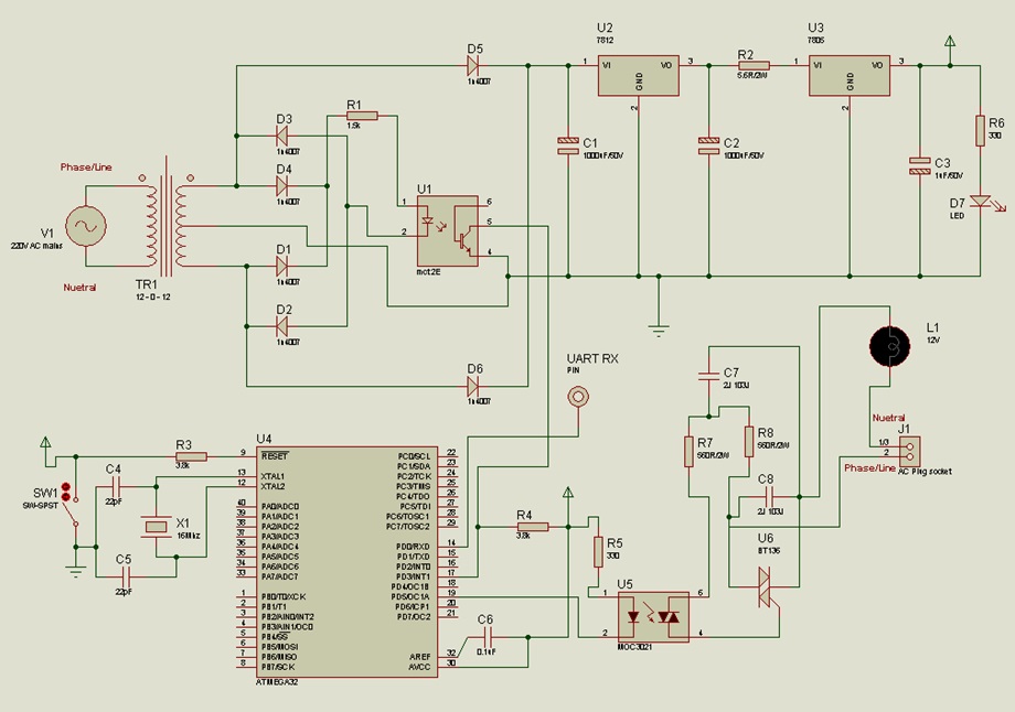 |
| Circuit-Diagram-AVR-ATMega32-Based-PC-Controlled-AC-Power-Supply_0 | 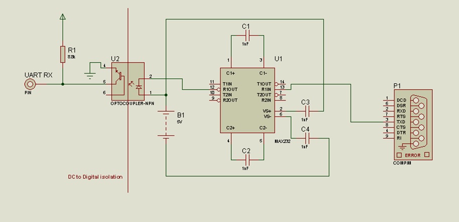 |
Project Datasheet
Project Video
Filed Under: Electronic Projects
Filed Under: Electronic Projects

Questions related to this article?
👉Ask and discuss on EDAboard.com and Electro-Tech-Online.com forums.
Tell Us What You Think!!
You must be logged in to post a comment.