DC motors are commonly used in electronics projects. A lot of projects require controlling the speed and direction of rotation of DC motors. The DC motors have voltage and RPM ratings. The RPM (Rounds Per Minute) rating indicates the maximum speed with which the motor can rotate. The speed of a DC motor varies with the voltage supplied to it. The motor rotates for the maximum speed when it gets the supply equal to its voltage rating. For supply voltages lower than their voltage rating, DC motors rotate at lower speeds. For example, a DC motor with 18V 200 RPM rating can rotate at maximum speed of 200 RPM when supply voltage to it is 18V. For supply voltage lower than 18V, it rotates at lower speeds.
The microcontrollers can vary the periodic duration of supply voltage resulting in an overall lower voltage level using pulse width modulation. The L293D IC is most commonly used to interface DC motors with the microcontrollers. The speed of DC motor can be controlled by control switching supply voltage to the motor from the enable pin of the IC. When a DC motor gets continuous supply from the L293D IC, it rotates for the maximum speed. When the voltage is supplied through non-continuous pulses, the speed of motor is decreased. The speed of a DC motor is controlled in this project based on the same technique. For speed regulation, microcontroller needs a control input which here is feed through an accelerometer.
The sensor is expected to be tied on palm and by rotating the palm in upward or downward direction, actually varying the X-axis coordinate, the speed of DC motor will decrease or increase respectively. The project is built on Arduino UNO and the Arduino sketch reading X-axis value from the accelerometer sensor and generating a PWM signal is written on Arduino IDE. The current rotational speed of the DC motor is displayed on an LCD screen scaled to a 10-bit number as the in-built ADC channel is 10-bit long. The code is burnt to the board using AVR Dude.
Components Required –
1. Arduino UNO
2. DC motor
3. Accelerometer GY-61
4. Motor driver IC-L293D
5. Connecting Wires
6. 16X2 LCD display
Block Diagram –

Fig. 1: Block Diagram of Arduino based Accelerometer driven DC Motor Speed Controller
Circuit Connections –
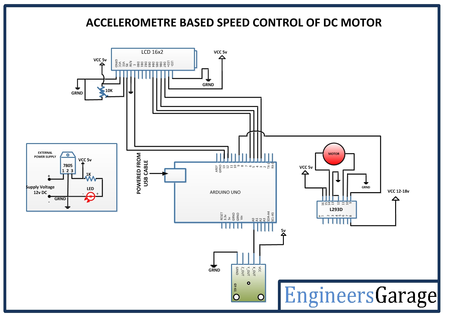
The circuit is built around Arduino UNO and has the following sections assembled together –
Power Supply – The Arduino board and other modules and sensors need 5V DC supply. The required DC voltage is supplied by a battery. The supply from the battery is regulated to 5V DC using 7805 IC. The IC has three pins – pin 1 should be connected to the anode of the battery, pin 2 and 3 with the cathode (common ground). The 5V DC should be drawn from the pin 3 of the IC. An LED along with a 10K Ω pull-up resistor can also be connected between common ground and output pin to get a visual hint of supply continuity.
16X2 LCD: The 16X2 LCD display will be used to display the increment or decrement of motor speed. It is connected to the Arduino board by connecting its data pins to pins 3 to 6 of the Arduino board. The RS and E pins of the LCD are connected to pins 13 and 12 of the Arduino UNO respectively. The RW pin of the LCD is grounded.

Fig. 2: Table listing circuit connections between Arduino Uno and Character LCD
The standard open-source library for interfacing LCD with Arduino UNO is used in the project. The library works as expected and needs no changes or modifications.
Accelerometer GY-61 – GY-61 is the accelerometer sensor used in the project. The sensor has five terminals for ground, VCC, X-axis Analog output, Y-axis Analog Output and Z-axis Analog Output. The VCC and ground are connected to common VCC and ground respectively and only X-axis Analog Output is utilized and interfaced to A0 pin of the Arduino board.
L293D DC Motor Driver IC – The L293D is the motor control driver IC. It has 16 pins with following pin configuration:

Fig. 3: Table listing pin configuration of L29D Motor Driver IC
The DC motor controlled in the circuit will be connected between pins 11 and 14 of the IC.
The L293D IC controls the DC Motors according to the following truth tables:

Fig. 4: Truth Table of L293D Motor Driver IC
Fig. 5: Truth Table of L293D Motor Driver IC
The pin 10 of the L293D is grounded while pin 15 is connected to VCC, therefore the DC motor connected between pins 11 and 14 is configured to rotate clockwise.
The pin 16 (VSS) is connected to 5V DC and pin 8 (VS) is connected to 12V DC supply. The pins 12 and 13 are grounded. The pin 9 (enable pin for motor) is connected to the pin 9 of the Arduino board to receive PWM signal.
How the project works –
When the Arduino board is powered ON, the Arduino sketch loads the required libraries and start flashing initial messages on the LCD screen. The initial messages shown on the LCD screen are to tell the name of the application. The same time Arduino writes a PWM signal at pin 9 to start rotating the DC motor at a pre-determined speed. The Arduino continuously read the analog voltage at A0 pin which changes on tilting the accelerometer sensor. The read analog voltage is converted to a digital reading through an ADC channel and utilized to change the duty cycle of PWM signal.
When the sensor is tilted upwards, the voltage representing X-coordinate is reduced and so the digitized reading. The digitized reading is a 10-bit number and the number obtained programmatically is compared to lie in a range of pre-set constants. If the digitized voltage reading falls within lower range of value, the duty cycle of PWM signal is decreased reducing the speed of the motor.
When the sensor is tilted downwards, the voltage representing X-coordinate is increased and so the digitized reading. The reading is again compared but with higher range of values and the duty cycle of the PWM signal is increased increasing the speed of the motor. Check out the Arduino sketch to know how analog voltage from accelerometer sensor is read and digitized through in-built ADC channel and compared to change duty cycle of PWM output.
Programming Guide –
First the Arduino sketch imports LiquidCrystal.h library and an object of Liquid Crystal class is declared with Arduino pins interfaced to LCD module mapped with the object. A constant representing delay time is declared and variable representing PWM output is assigned to pin 9 of Arduino. Some counter variables are declared and a variable to represent pre-determined speed constant in terms of digitized 10-bit number is declared.
#include <LiquidCrystal.h>//import the LCD library
LiquidCrystal lcd(13, 12, 6, 5, 4, 3);// Pins used for RS,E,D4,D5,D6,D7
#define delayT 300
int PWM=9; //Digital pin 9 is used to ON relay 4
int a, pos=0;
unsigned char spd=50;
A setup() function is called in which baud rate for serial transmission with LCD module is set to 9600 bits per second using Serial.begin() method. The LCD object is initialized to 16 by 2 character mode using lcd.begin() method. The Arduino pin giving PWM pulse is set to digital output using pinMode() function and the pre-set constant speed factor is passed as duty cycle argument to analogWrite() function. Some initial messages are flashed on the LCD showing the name of the application and current speed factor after few seconds.
void setup() {
Serial.begin(9600);
lcd.begin(16,2);//LCD 16×2 initialization
pinMode(PWM, OUTPUT);
analogWrite(PWM, spd);
lcd.setCursor(0,0); //Initially set the cursor position of LCD to 1st Columb 1st row.
lcd.print(“Engineers Garage”);//After initialising print data
lcd.setCursor(0,1); //Initially set the cursor position of LCD to 1st Columb 2nd row.
lcd.print(” “); //print blank to clear all the data on LCD
delay(3000);
lcd.setCursor(0,0);
lcd.print(” ACCELEROMETER “);
lcd.setCursor(0,1);
lcd.print(” SPEED CONTROL “);
delay(3000);
lcd.setCursor(0,1);
lcd.print(” “);
delay(3000);
lcd.setCursor(0,0);
lcd.print(” MOTOR SPEED “);
}
The loop() function is called in which the voltage reading from the X-axis terminal of the accelerometer module is digitally read using analogRead() function and assigned to variable holding speed factor. The value of the variable is displayed on the LCD screen. The value is compared to exist between 173 and 175 or lie above 175 or below 173 and accordingly is modified and passed as duty cycle argument to analogWrite() function increasing or decreasing the speed of the DC motor. The increased or decreased speed factor is displayed on the LCD screen simultaneously.
void loop() {
spd=analogRead(A0)*(5.0/1023.0)*100;
lcd.setCursor(0,1);
printDigits(spd);
if(spd>=173 && spd<=175){
analogWrite(PWM,170);
lcd.setCursor(6,1);
printDigits(spd);}
else if(spd>175){
analogWrite(PWM,spd+10);
lcd.setCursor(6,1);
printDigits(spd+10);}
else if(spd<173){
lcd.setCursor(6,1);
analogWrite(PWM,spd-80);
printDigits(spd);}
else;
}
A printDigit() function is used in the loop() function to format the speed factor representation with padded zeros.
void printDigits(int digits) //this void function is really useful; it adds a “0” to the beginning of the number, so that 5 minutes is displayed as “00:05:00”, rather than “00:5 :00”
{
if(digits < 10)
{
lcd.print(“0”);
lcd.print(digits);
}
else
{
lcd.print(digits);
}
}
This completes the Arduino sketch for Accelerometer driven DC Motor Speed Control Project.
Project Source Code
###
//Program to #include <LiquidCrystal.h>//import the LCD library LiquidCrystal lcd(13, 12, 6, 5, 4, 3);// Pins used for RS,E,D4,D5,D6,D7 #define delayT 300 int PWM=9; //Digital pin 9 is used to ON relay 4 int a, pos=0; unsigned char spd=50; void setup() { Serial.begin(9600); lcd.begin(16,2);//LCD 16x2 initialization pinMode(PWM, OUTPUT); analogWrite(PWM, spd); lcd.setCursor(0,0); //Initially set the cursor position of LCD to 1st Columb 1st row. lcd.print("Engineers Garage");//After initialising print data lcd.setCursor(0,1); //Initially set the cursor position of LCD to 1st Columb 2nd row. lcd.print(" "); //print blank to clear all the data on LCD delay(3000); lcd.setCursor(0,0); lcd.print(" ACCELEROMETER "); lcd.setCursor(0,1); lcd.print(" SPEED CONTROL "); delay(3000); lcd.setCursor(0,1); lcd.print(" "); delay(3000); lcd.setCursor(0,0); lcd.print(" MOTOR SPEED "); } void loop() { spd=analogRead(A0)*(5.0/1023.0)*100; /* lcd.setCursor(0,1); printDigits(spd); lcd.setCursor(0,1); lcd.print(a); delay(delayT); b=analogRead(A1)*(5.0/1023.0)*100; lcd.setCursor(6,1); lcd.print(b); delay(delayT); c=analogRead(A2)*(5.0/1023.0)*100; lcd.setCursor(12,1); lcd.print(c); delay(delayT); */ if(spd>=173 && spd<=175){ analogWrite(PWM,170); lcd.setCursor(6,1); printDigits(spd);} else if(spd>175){ analogWrite(PWM,spd+10); lcd.setCursor(6,1); printDigits(spd+10);} else if(spd<173){ lcd.setCursor(6,1); analogWrite(PWM,spd-80); printDigits(spd);} else; } void printDigits(int digits) //this void function is really useful; it adds a "0" to the beginning of the number, so that 5 minutes is displayed as "00:05:00", rather than "00:5 :00" { if(digits < 10) { lcd.print("0"); lcd.print(digits); } else { lcd.print(digits); } }###
Circuit Diagrams
Filed Under: Electronic Projects

Questions related to this article?
👉Ask and discuss on EDAboard.com and Electro-Tech-Online.com forums.
Tell Us What You Think!!
You must be logged in to post a comment.