Detecting the physical conditions of a robot is always useful in robotic applications. Particularly if the robot is a rover and is designed to explore different terrains. In such applications, there are instances when the state of the robot has to be detected. It may involve detection of collision or fall, change in orientation of the robot’s body, detection of direction of the navigation, or detection of the state of the robot with respect to the surrounding terrain, etc. Detection of fall or collision is one of such important state changes. If a robot is designed to explore outdoors, it gets important to know if a robot has collided from a side or fallen on a side. This can be used to take intuitive actions in response to such events.
Detection of fall or collision on the part of the robot body can be especially crucial in the design of battle bots. Battle bots are designed to win against other bots in a robotic battle. By detecting impact or collision on specific parts of the robotic body, a battle bot can be designed to take autonomous actions for rescue, stabilization, or actuate against the charge.
In this project, we have designed a collision/fall detection circuit using Arduino and Knock sensor. The knock sensor can be handy in detecting such impacts like collision or falling. A knock sensor is sensitive to vibrations and can provide early warning before complete destabilization or damage if installed appropriately in a rover’s mechanical assembly. Let us test an impact detection circuit with a popular KY-031 knock sensor.
Components required
- Arduino UNO x1
- KY-031 Knock Sensor x1
- LED x1
- Resistor 330Ω x1
- Connecting wires/jumper wires
- Breadboard
- Power supply for Arduino
Circuit connections
In this project, Arduino is interfaced with a knock sensor to detect any impact like collision or fall. The knock sensor used in the circuit is KY-031. The sensor has three terminals – Signal, VCC, and GND. The Signal terminal is indicated by the ‘S’ label, the middle one is VCC, and the GND is indicated by ‘-‘ label on the sensor.
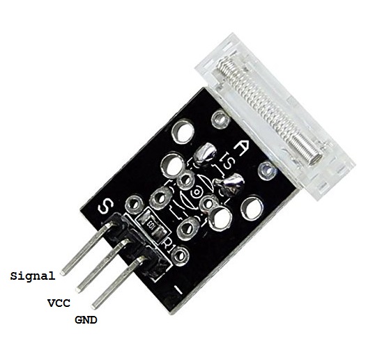
Pin diagram of KY-031 Knock sensor
For interfacing, the KY-031 knock sensor with Arduino connects the S pin to any of the Arduino’s GPIO, pin 7 in this case, and connects the VCC and GND pins to 5V out and one of the GND pins of Arduino, respectively. For an indication of the impact, a LED is interfaced at pin 6 of the Arduino UNO. The LED is interfaced such that it sources current from the Arduino pin. A current limiting resistor is connected in series to the LED for its protection.
Circuit diagram
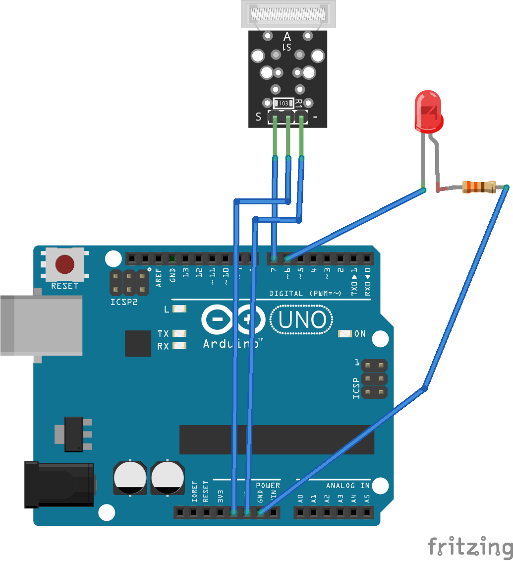
Circuit diagram of Arduino based Fall/Collision/Shock detector
Arduino Sketch
How it works
A knock sensor is a vibration sensor that detects vibrations or shocks when tapped or knocked. One of the popular knock sensors is KY-031. This simple and cheap knock sensor can be easily interfaced with any microcontroller or single-board computer. It has a digital output that, on powering up the sensor, remains HIGH by default. Whenever there is a shock or impact, the sensor’s digital output goes LOW for the moment.
The KY-031 knock sensor actually has a conductive vibrating spring. This spring acts as a switch within the sensor and remains open-circuit by default. When there is a shock or impact, the spring is vibrated for a moment and touches a contact-making a closed connection. By default, the sensor output is pulled HIGH via a 10K resistor. When the vibrating spring touches the contact, the output is driven to LOW. A simplified representation of the knock sensor is shown below.
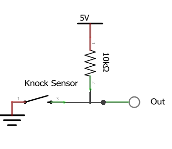
Internal block diagram of KY-031 Knock sensor
The knock sensor is not much sensitive device. It can only detect hard vibrations or shocks. Therefore, it can be useful in detecting collisions or falls. It can also be used as a door knock sensor.
In the circuit, the output of the knock sensor is connected to Arduino’s pin 7. As the sensor is pulled high by default and only outputs a LOW on shock or vibration, Arduino is programmed to pool for a logical LOW at the respective pin. Whenever there is LOW signal at the Arduino’s pin 7, it sets the pin 6 HIGH, lighting up a LED. This gives a visual indication of the detected impact to the sensor.
In a robotic application, the knock sensor can be tied to the robot’s body, so any shock or vibration to the body is transferred to it. In a robotic application, instead of glowing a LED, a counter action like activating some actuators to stabilize the robot’s body or counter attack (like in the case of battle robots) can be initiated.
The code
The sketch is pretty simple. It begins by declaring pins connected to the knock sensor and the LED. Variables – ‘knockDetect’, ‘impactAlarm’, and ‘lastKnockTime’ are declared to detect knock/tapping signal logic, flag status of impact, and record time elapsed from the last impact in milliseconds, respectively.
In the setup() function, the baud rate for serial messaging is set to ()9600 using Serial begin() method, LED pin is set as output while the Knock pin is set as input.
In the loop(0 functions, Arduino pools for a logical LOW signal at the knock pin. If there is a logical low, a message indicating detection of impact is passed to the serial port, LED is turned on by passing a HIGH logic at pin 6, and impactAlarm flag is set True. If no LOW signal is detected in a loop iteration since 500 milliseconds from the last impact, a message indicating no impact is passed to the serial port, LED is turned OFF by passing a LOW logic at pin 6, and impactAlarm flag is set False.
Result
The following demonstration shows the working of the circuit when the knock sensor is dropped over a surface.
Filed Under: Electronic Projects, Sensors, Tutorials, Video

Questions related to this article?
👉Ask and discuss on Electro-Tech-Online.com and EDAboard.com forums.
Tell Us What You Think!!
You must be logged in to post a comment.