In this tutorial, we’ll learn how to send a text message using an STM32 microcontroller and SIM900 GSM module. The SIM900 can communicate with an external controller by using the universal asynchronous receiver-transmitter (UART) interface. This means that any controller with a UART module can “talk” with the module.
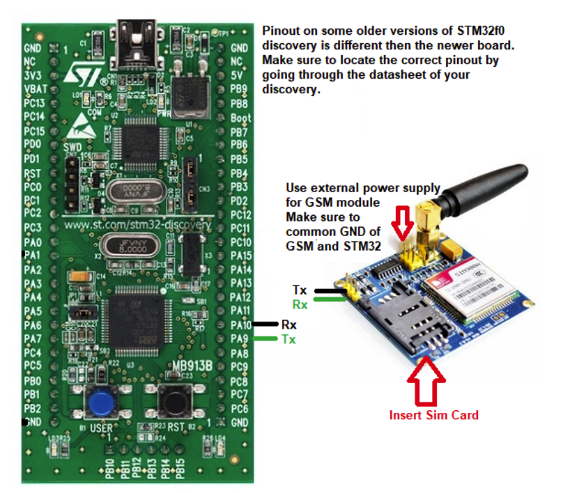
Fortunately, most STM32 microcontrollers have one or more UART peripherals. For this project, we’ll use the STM32f0xx discovery board with the STM32F051R8 microcontroller. The STM32’s are 3.3 volts tolerant and most SIM900s are 5 volts tolerant. There are, however, 3.3V modules available, which is what we’re using to avoid extra circuit components.
We’re also using the STM32CubeMX code configurator IDE for STM32F051R8 peripheral initialization. The STM32CubeMX offers an excellent resource where we can graphically initialize the peripherals and import the initialization code. We can, then, include our own code.
The STM32CubeMX initialization
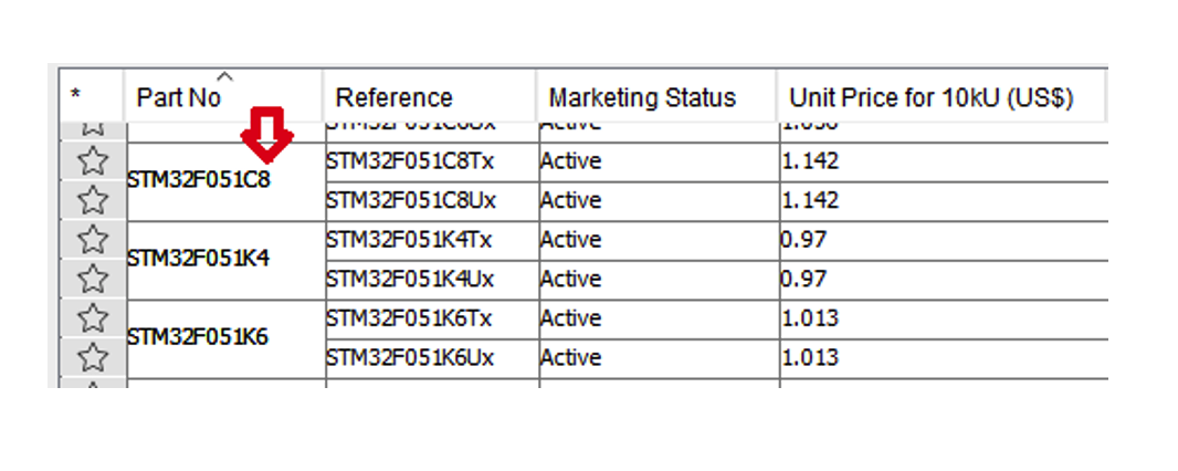
Open the STM32CubeMX and select the microcontroller or board (discovery, Nucleo, etc.) that you’re using for this project, ensuring you pick the correct one. If that microcontroller fails to appear in the list, you’ll need to install the package containing the particular micro.
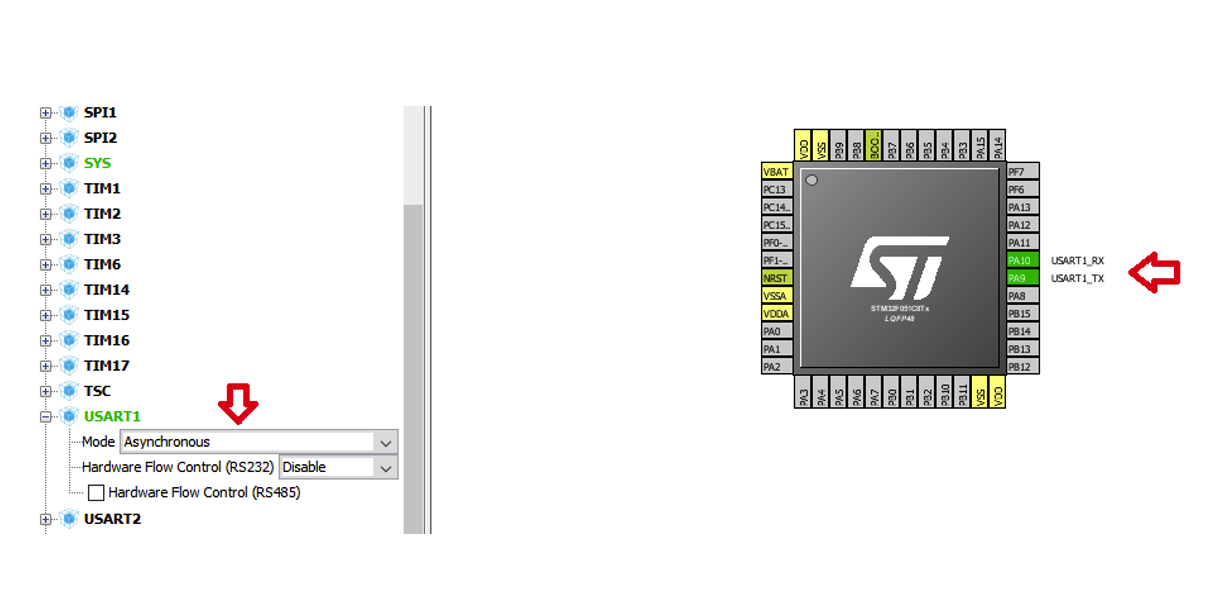
Double click on the microcontroller and a 3D view of it will appear on the screen. From here, you can set the individual pin functions, timers, clock speed, and other relevant settings. As we require the UART for serial communication with the GSM module, we enabled it, which makes the micro pins appear green.
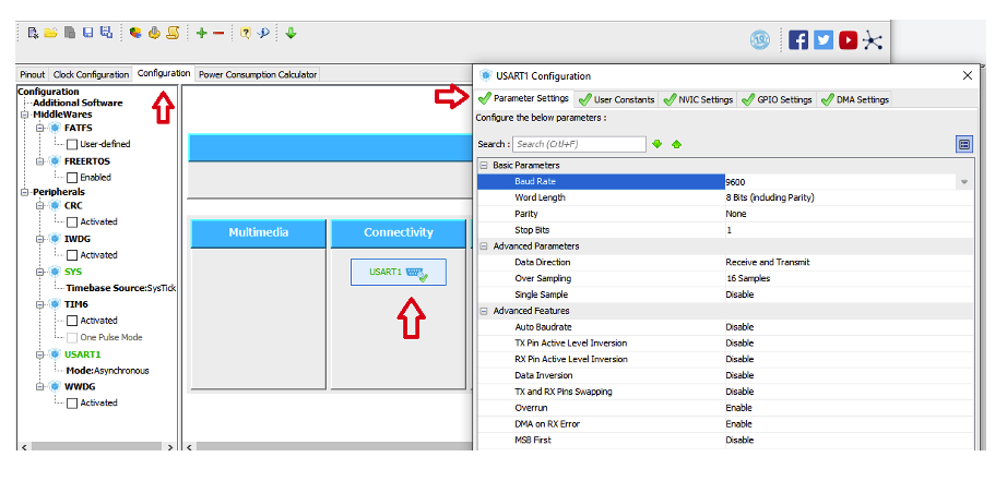
For the UART parameter settings, click the UART 1 and then the parameter settings. We set the baud rate to 9600 bps, the parity to none, and the stop bit to 1. From the UART, it’s possible to take as many functions as the STM offers to include as UART features.
For this project, we’re keeping it simple and only using the UART as a basic communication protocol without advanced features.
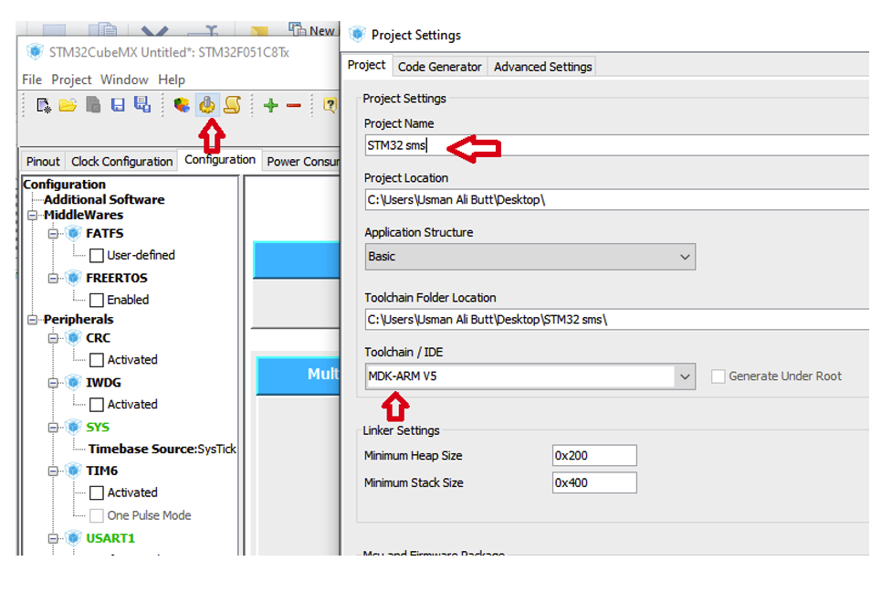
To generate the code, press the gear icon from the menu. Give the project a name and select the tool chain IDE that you’ll work on to write and debug the code. We’re using a Keil IDE with a microcontroller development kit (MDK) ARM v5.
Afterward, click OK. The project files with your settings will be generated at the desired address.
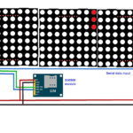
Circuit diagram
The code
Navigate to the folder where the project files were generated. Open the “Keil” project. On the left-hand side of the project, you’ll find a file tree. If you expand the “Application/User” folder, you can access the main file. Open it.
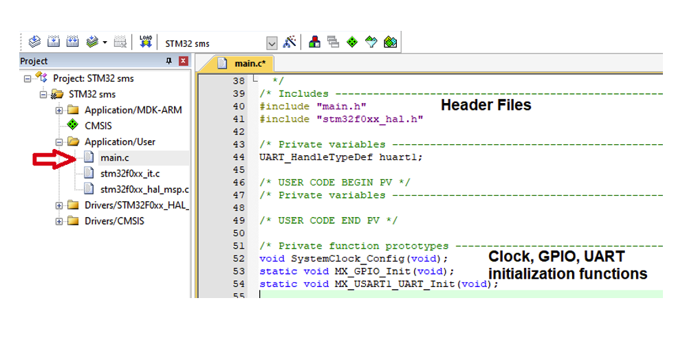
All of the required header files and initialization functions are declared in the main file. The initialization functions are called in the main function. The header file, “stm32f0xx_hal.h,” is in the HAL libraries. These libraries are provided by STMicroelectronics. In fact, it’s possible to view all of the library functions by expanding the “Drivers/STMF0xx_HAL_Driver” folder.
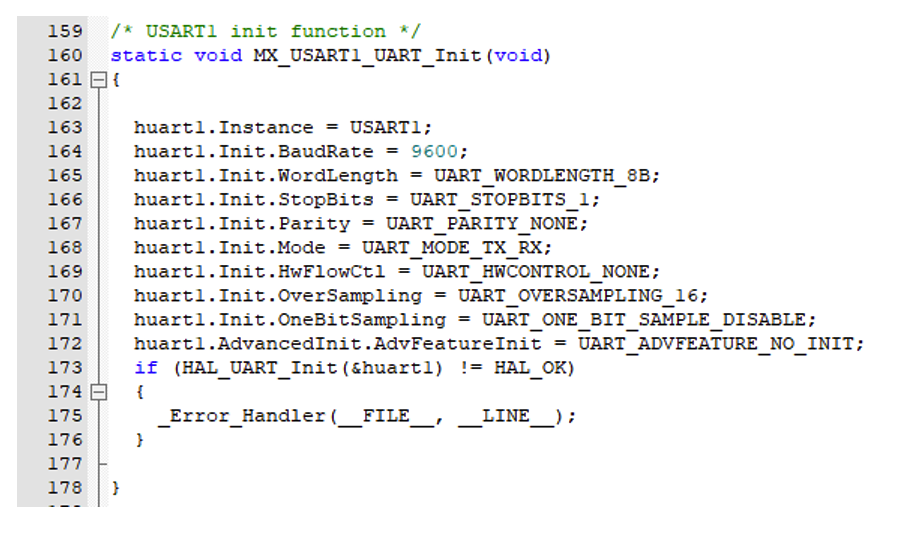
The UART initialization function is below. The code is generated by the STM32CubeMX as we made all of the settings in the graphic user interface. The baud rate is 9600bps, the stop bit is 1, and the parity is none — which call all be verified in the code.
Now, let’s jump to the main function. As you’ll note in the above code, we declared some character arrays. Each character array is holding a command for the GSM module. The SIM900 module works on the AT command set. The commands required to send an SMS are explained in the code.
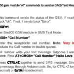
To test the module, the “AT” command is sent. If the GSM replies with “OK,” then we’re good to go. However, if an “ERROR” message is received instead, then the GSM module is faulty or there might be another problem (such as with the power or network, etc.).
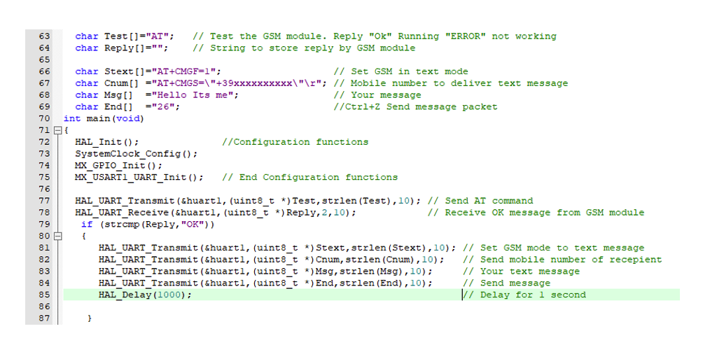
The HAL_UART_Transmit function from the HAL library sends the data via UART’s TX pin. It must be given the proper parameters. The first one is the UART handler structure name, which is defined in the UART library and assigned in the main file. The second parameter is the data/string. The third parameter includes the length/size of the data/string. We used the strlen() string length function to calculate the size.
The final parameter is the time from the data transmission, which we set to 10 milliseconds.
What happens is the strcmp() string function compares the GSM’s reply with ”OK.” When this reply matches, then it enters it in the “if loop,” sending the SMS.
The GSM sends the SMS as a packet. To complete the full packet, it’s necessary to supply it with the receiver’s mobile number, followed by the text message that you’d like to send.
The end command (ctrl+Z) is extremely important as it’s what tells the GSM module to send the SMS.
Reading a received SMS is just like sending one, except for the command: AT+CMGR, AT+CMGL. However, there are several possible variations for receiving and reading, including:
- Read the last received message.
- Read the last received message from a particular number.
- Read unread message (Then first second or third).
Note: typically, sim cards store up to 32 SMS’s. Any additional messages are stored in a smartphone’s memory and can be restored if requested by the user. It’s also possible that certain sim cards do no hold SMS messages.
So, the ideal way to read and verify if an SMS is possible is to use the STM32 in debug mode. Put the “read” variables in the debug window and wait for the message output.
Where to buy the parts:
You may also like:


Filed Under: Microcontroller Projects

Questions related to this article?
👉Ask and discuss on Electro-Tech-Online.com and EDAboard.com forums.
Tell Us What You Think!!
You must be logged in to post a comment.