In the previous tutorial, we learned how to use digital input with Raspberry Pi. Raspberry Pi (RPi), as an embedded computer, is capable of digital input, digital output, pulse width modulation (PWM), and the implementation of several serial communication protocols (such as UART/USART, I2C, and SPI).
In this tutorial, we’ll cover analog output by using PWM with RPi. Later, we will use PWM feature of Raspberry Pi to blink and fade an LED.
PWM
Most microcontrollers and single-board computers (including Arduino and RPi) cannot generate a true analog signal. This is because generating this signal requires complex circuitry that’s not easily integrated with low-cost microcontrollers or SBCs.
However, controllers and embedded computers often require controlling devices or actuators that use non-periodic analog input. That is why single-board controllers and computers are typically equipped with a PWM feature.
The pulse-modulated signal is an approximation of an analog signal in a defined range of voltage. Generally, the PWM output generated by controllers/SBCs is unipolar and has a peak voltage approximation of 5 or 3.3V, depending upon the development board.
PWM signals are periodic rectangular signals of fixed (or set) frequency where the duty cycle can be altered. By altering the duty cycle of a fixed-frequency periodic rectangular wave, the signal can approximate to analog voltage levels in a defined range. The maximum analog voltage that a signal can approximate is the amplitude of the rectangular wave.
Any other voltage levels that a PWM signal can approximate depends on the allowed variation in the duty cycle. For example, let say the amplitude of a PWM signal is 5V. If the duty cycle is controlled by an 8-bit register, 256 (2^8) voltage levels can be achieved between 0 to 5V. Now, if we assume these voltage levels are precisely spaced by equal intervals, each voltage level will differ by 19.6 mV (5V/255) from the adjacent voltage levels.
On the other hand, if the duty cycle is controlled by a 10-bit register of the same amplitude, then 1024 (2^10) voltage levels can be achieved between 0 and 5V. In this case, each voltage level will differ by 4.9 mV from the adjacent voltage levels.
The frequency of the PWM signal does not have any impact on the number of voltage levels that can be achieved by a signal. Although the higher is the frequency of the PWM signal, the better the precision of the voltage level. The frequency of the PWM signal also plays an important role when the signal is used for high-speed switching operations in a circuit or audio applications.
PWM signals are used in several embedded applications, such as controlling the speed of a DC motor, a servo motor, or fading an LED.
Analog output in PWM
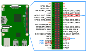
Raspberry Pi is similar to most other single-board computers and microcontrollers — it’s unable to generate true analog output. However, RPi can generate software PWM on every one of its 26 GPIO pins. It can also generate hardware PWM signals at the:
- GPIO12 (board pin number 32)
- GPIO13 (board pin number 33)
- GPIO18 (board pin number 12)
- GPIO19 (board pin number 35).
The hardware PWM uses the system timer of Broadcom SoC and can generate a PWM signal with a maximum frequency of 19.2 MHz.
This image shows the RPi channels where the hardware PWM is available:
The software PWM is available on all 26 of RPi’s GPIO and can generate PWM frequencies from 1 Hz up to few kiloHertz. The duty cycle of the software PWM signals can be varied between 0.0 and 100.0.
For generating hardware PWM signals, it’s necessary to import the pigpio library. However, the software PWM signals can be generated simply by importing the RPi.GPIO library.
In this tutorial, we’ll learn how to generate the software PWM signals.
Using Python to generate software PWM signals
It’s possible to generate software PWM on RPi’s channels using the RPi.GPIO library, thanks to the py_pwm.c, py_pwm.h, soft_pwm.c and soft_pwm.h files (included in the RPi.GPIO library’s source code).
The library supports the following Python functions for generating and controlling software PWM on RPi:
The GPIO.PWM() method
This function is used to create a PWM instance. It requires two arguments:
1. The channel number where the PWM signal has to be generated
2. The PWM signal frequency in Hertz. The instance must be created by assigning the method to a variable.
This function/method has this syntax:
soft_pwm = GPIO.PWM(channel, frequency)
The channel number must be specified according to the Board or BCM numbering set in the user-program.
The start() method
This method can be applied to an instance of the software PWM. It takes only one argument: the duty cycle of the PWM signal.
When calling this method on a PWM instance, Python program starts a software PWM signal at the given channel with the specified duty cycle.
Here’s the syntax:
soft_pwm.start(duty cycle)
The ChangeFrequency() method
This method can be applied to an instance of the software PWM. It takes only one argument: a new frequency of PWM signal in Hertz.
When calling this method on a PWM instance, Python program changes the frequency of the PWM output to the specified frequency.
Here’s the syntax:
soft_pwm.ChangeFrequency(frequency)
The ChangeDutyCycle() method
This method can be applied to an instance of the software PWM. It takes only one argument: a new duty cycle.
The value of the duty cycle can be between 0.0 and 100.0. When calling this method on a PWM instance, Python program changes the duty cycle of the PWM signal to the specified duty cycle.
This method has this syntax:
soft_pwm.ChangeDutyCycle(duty cycle)
The stop() method
This method can be applied to an instance of software PWM. It takes no arguments. When calling this method on an instance, the PWM signal is stopped at the respective channel.
This method has this syntax:
soft_pwm.stop()
Recipe: LED blinking using PWM
In this recipe, we will blink an LED on Raspberry Pi using the software PWM.
Components required
1. Raspberry Pi 3/4 Model B x1
2. LED x1
3. 330 Ohms resistor x1
4. Breadboard x1
5. Male-to-female jumper wires
Circuit connections
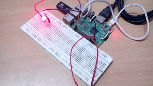
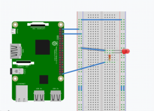
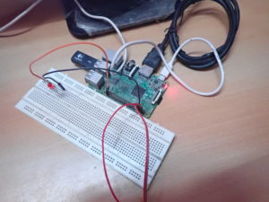
First, connect the GPIO21 (board pin number 40) of Raspberry Pi with the anode of the LED. Next, connect the cathode of the LED with a series resistor of 330 Ohms and then ground the other terminal of the resistor.
The DC supply voltage and ground can be given to the circuit from pin numbers 2 and 6 of the Pi board, respectively.
Python script
import RPi.GPIO as GPIO
GPIO.setmode(GPIO.BOARD)
GPIO.setup(40, GPIO.OUT)
soft_pwm = GPIO.PWM(40, 1)
soft_pwm.start(50)
input(“Press return to stop: “)
soft_pwm.stop()
GPIO.cleanup()
Working the project
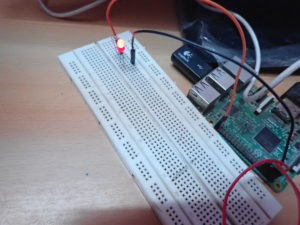
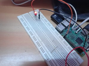
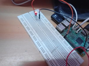
An LED is interfaced at pin 40 of RPi’s GPIO header. It’s connected so RPi’s channel must source current to turn it ON. In the Python script, a software PWM signal of 1 Hertz frequency is generated, with a 50 percent duty cycle.
The 1 Hertz means the PWM signal will have a time period of one second. With the 50 percent duty cycle, the channel will output a HIGH signal for 500 milliseconds and then a LOW signal for another 500 milliseconds. This is turning the LED on for 500 milliseconds and then off for the following 500 milliseconds.
Therefore, the LED will continuously blink at an interval of one second.
 Programming guide
The Python scripts start by importing the RPi.GPIO library. RPi’s pin numbering is set to the board numbers by using the GPIO.setmode() function. However, the board pin 40 is set as an output pin using the GPIO.setup() method.
import RPi.GPIO as GPIO
GPIO.setmode(GPIO.BOARD)
GPIO.setup(40, GPIO.OUT)
An instance of the software PWM of 1 Hertz is created at board pin 40 by using the GPIO.PWM() method. The duty cycle of the software PWM instance is set to 50 percent by using the start() method.
An input() function is called to terminate the script when the user presses the return key. Once the input is received, the PWM signal is stopped by using the stop() method, and the GPIO pins are cleaned up using the GPIO.cleanup() method.
soft_pwm = GPIO.PWM(40, 1)
soft_pwm.start(50)
input(“Press return to stop: “)
soft_pwm.stop()
GPIO.cleanup()
Demonstration video
Recipe: LED fading using PWM
In this recipe we will fade an LED using the software PWM with Raspberry Pi.
Components required & circuit connections
These are both the same as in the previous recipe.
Python script
import RPi.GPIO as GPIO
import time
GPIO.setwarnings(False)
GPIO.setmode(GPIO.BOARD)
GPIO.setup(40, GPIO.OUT)
soft_pwm = GPIO.PWM(40, 50)
def setup():
soft_pwm.start(0)
def loop():
for dc in range(0, 100, 1):
soft_pwm.ChangeDutyCycle(dc)
time.sleep(0.1)
for dc in range (100, 0, -1):
soft_pwm.ChangeDutyCycle(dc)
time.sleep(0.1)
def endprogram():
soft_pwm.stop()
GPIO.cleanup()
if __name__ == ‘__main__’:
setup()
try:
loop()
except KeyboardInterrupt:
print(“Keyboard Interrupt Detected”)
endprogram()
Working the project
To fade an LED, it’s necessary to apply an analog signal that approximates to the rectified sine wave. To learn more about this, check out the LED fading recipe using Arduino.
With RPi, we’re using a modified sine wave by generating a software PWM signal of 50 Hertz. At this frequency, the signal has a 20-millisecond time period. The frequency doesn’t change throughout the application.
To create the rectified sine wave, the duty cycle of the software PWM must increase from 0 to 100 in increments of one. Each step or increment is applied for 0.1 seconds, wherein five pulse trains of the PWM signal are applied to the LED.
Then, the duty cycle is decreased from 100 to 1 in increments of -1. Five PWM pulse trains are applied for 0.1 seconds of each increment. The user-program is made to iterate infinitely using try-exception statement until a keyboard interrupt is received.
Programming guide
The script begins by importing the RPi.GPIO and the time libraries. The GPIO warnings are set to false using the GPIO.setwarnings() method.
RPi’s pin numbering is set to the board numbers by using the GPIO.setmode() function. The board pin 40 is set as an output pin using the GPIO.setup() method. But the board pin 40 is instantiated as the software PWM using the GPIO.PWM() method.
import RPi.GPIO as GPIO
import time
GPIO.setwarnings(False)
GPIO.setmode(GPIO.BOARD)
GPIO.setup(40, GPIO.OUT)
soft_pwm = GPIO.PWM(40, 50)
A user-defined setup() function is written so that the software PWM has a 0 percent duty cycle beginning at the PWM instance. This function is only run only once.
def setup()
soft_pwm.start(0)
A user-defined loop() function is written, wherein the duty cycle of the PWM signal is changed from 0 to 100, and then back to 0. This occurs in steps of one, for an interval of 0.1 seconds, during each increment.
This function iterates infinitely so that the LED lights and fades for an infinite number of times.
def loop():
for dc in range(0, 100, 1):
soft_pwm.ChangeDutyCycle(dc)
time.sleep(0.1)
for dc in range (100, 0, -1):
soft_pwm.ChangeDutyCycle(dc)
time.sleep(0.1)
The function endprogram() is written to stop the PWM signal when a keyboard interrupt is received. It then cleans the Raspberry Pi GPIO.
def endprogram():
soft_pwm.stop()
GPIO.cleanup()
The functions defined above are called in a try-exception statement, such that the setup() function runs once, while the loop() function keeps iterating until a keyboard interrupt is received.
if __name__ == ‘__main__’:
setup()
try:
loop()
except KeyboardInterrupt:
print(“Keyboard Interrupt Detected”)
endprogram()
Demonstration video
In the next tutorial, we’ll discuss using serial communication with Raspberry Pi.
Filed Under: Raspberry pi


Questions related to this article?
👉Ask and discuss on EDAboard.com and Electro-Tech-Online.com forums.
Tell Us What You Think!!
You must be logged in to post a comment.