In the previous tutorial, we learned how to generate analog output in the form of software PWM when using Raspberry Pi (RPi). We also showed how software PWM can be used to fade an LED.
The PWM output can also be used for other applications, such as for speed control of a DC motor or controlling a servo motor. As an embedded computer, RPi is capable of digital input, digital output, PWM, and implementation of various serial communication protocols (such as UART/USART, I2C, and SPI).
The universal asynchronous receiver/transmitter or UART is the most common serial communication protocol used by embedded devices. In this tutorial, we’ll cover the basics of serial communication and review several serial communication options with RPi.
What is serial communication?
Serial communication refers to the sequential transfer of data over a wire. A nibble or byte is the smallest unit of information. A byte is made up of 8 bits whereas a nibble comprises 4 bits. Larger units include kilobytes, megabytes, gigabytes, and so on.
Data communication between two devices can be wired or wireless. In wired communication, the data (information) is communicated between two devices over wires. These wires are called a data bus. The channels (pins) on a device (or component of a device) that communicate data are collectively called a communication port.
There can be two types of wired communication ports:
1. Parallel ports: data is communicated over parallel data lines
2. Serial ports: data is communicated as a bit-stream
A parallel port is useful for fast data communication of fixed-size data. For example, the data may consist of fixed-size units of 8, 16, 32, or 64-bit, etc. Additionally, a parallel port can provide high-transfer rates with 1 bit of data-unit on each wire of the parallel data bus and the parallel port.
On the other hand, a serial port can transfer data of fixed-units and communicate data of variable size. Where a parallel port uses complex circuitry for data communication, a serial port simplifies data communication by reducing the number of required channels for data transfer.
While general-purpose computers often use parallel ports for data communication because of their high transfer rates, embedded controllers and computers typically rely on serial ports. There are many reasons for this.
For one, serial ports involve less complex circuitry and can easily be integrated on a microcontroller or system on a chip (SoC). Also, embedded controllers/computers may interface with several devices, communicating with them in a single user program. It’s next-to-impossible to interface several external peripherals and devices with parallel ports because it would require several digital input/output (GPIO) pins.
However, it is possible to interface and communicate with hundreds of peripherals/devices using only two, three, or four channels of a serial port. There are serial communication protocols that support data transfer of fixed and variable data-packet size.
In general-purpose computing, parallel ports have typically been replaced with universal serial busses (USBs) for interfacing with external peripherals. The parallel interfaces for internal interfacing (such as ATA for interfacing with storage devices) have also been replaced with serial standards. These include Serial ATA (SATA), Serial Attached SCSI (SAS), and PCIe physical interfaces.
Data communication standards
A communication port refers to a channel (pin) or a group of channels (pins) on a controller/processor that’s responsible for communicating data with an interfaced peripheral/device. The data bus is the wire or group of wires over which the data is communicated between two devices — or between controller/processor and a peripheral/device.
The term “interface” typically refers to the electronic signaling and bus system used for data communication. RS-232, RS-422, RS-485, I2C, SPI, Microwire, CAN, 1-wire, and USB are examples of serial interfaces (i.e. these standards refer to the electronic signaling schemes and bus systems for serial data communication).
The term “protocols” refers to how the data is communicated, encoded, and decoded over the bus between the two devices, or between controller/processor and a device/peripheral. UART, USART, I2C, SPI, CAN BUS protocol, Microwire, 1-wire, and USB are examples of serial communication protocols (i.e. these standards refer to the encoding and decoding of data of serial data communication).
A standard may be an interface, a protocol, or both. For example, RS-232, RS-422, and RS-485 are serial interfaces that use a UART serial communication protocol. UART and USART are serial communication protocols that can be implemented by incorporating a UART/USART chip or a built-in UART/USART. The standards — such as I2C, SPI, CAN, Microwire, 1-Wire, and USB — are an interface and a protocol.
Specifications
To understand how a serial communication protocol/interface works, it’s important to first learn about the many specifications of serial communication standards.
In general, these specifications apply to all serial communication standards:
Asynchronous vs synchronous signaling
- Asynchronous signaling: if on a data bus, the data is sent without timing signals
- Synchronous signaling: if on a data bus, the data is sent with a timing clock (meaning the clock signals are passed through a dedicated channel)
Transmission mode
The transmission mode can be simplex, half-duplex, or full-duplex.
- Simplex: when the data can be only received or transmitted between the devices
- Half-duplex: when the data can be sent and received between the devices, but not at the same time
- Full-Duplex: when the data can be sent and received between devices, simultaneously
![]()
Communication type
Serial communication can be point-to-point, multi-point, multi-drop, master/slave, or multi-master.
- Point-to-point or peer serial communication: when two devices have point-to-point communication. This means one channel is dedicated to receiving data from the other device, and the other channel is dedicated to transmitting data to the other device. In point-to-point serial communication, there are only two peer transceivers across a bus (a group of wires, and only two wires in this case).
- Multi-point serial communication: when more than two peer transceivers have bi-directional communication over a common bus. This form of serial communication must include a mechanism for identification of the transceiver device to which another transceiver device must transmit or receive the serial data.
- Multi-drop serial communication: there are only one transmitter and multiple receivers of serial data sharing a common bus. This form of serial communication must have a mechanism to identify the receiver from the common bus system.
- Master/slave serial communication: one device is configured as the master and the other devices are configured as slaves. The master controls the slaves and can receive or transmit data to the slaves over a single channel or over two channels using a timing signal (synchronous signaling).
- Multi-master serial communication: there can be more than one master of the bus. This communication protocol must have a mechanism to avoid conflict between the masters for the use of the common serial bus.
The specifications of some common serial communication standards (interfaces/protocols) are summarized here:

Serial communication on RPi
In the previous tutorials on digital input and output, we transferred data parallel. The GPIO pins on RPi can be considered parallel data pins, capable of digital data communication over 3.3V TTL logic levels. However, these GPIO pins are not arranged as ports (8, 16, or 32-bit ports) like in a microcontroller.
Raspberry Pi can communicate serial data with other devices using some of the common serial communication protocols, such as UART, I2C, SPI, and USB. There are two UART ports/interfaces, two I2C ports (one for HATS and other for external devices), two SPI ports, and four USB ports on RPi 3B/4B.
UARTs on RPi
The universal asynchronous receiver/transmitter or UART is typically referred to as “serial port” in computer terminology. Raspberry Pi is no exception. For RPi, the serial port term also exclusively refers to the UART.
The Broadcom SoC on RPi models have two types of in-built UARTs:
1. PL011 UART
2. Mini UART
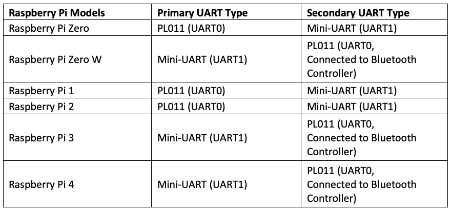
PL011 is 16550-compatible UART while the mini-UART has a reduced set of features. The RPi Zero, 1, 2, and 3 have two UART ports. One is the PL011 (UART0) and the other is the mini-UART type (UART1).
The RPi 4 has six UART ports of which five are PL011 types (UART0, UART2 to UART5) and one is the mini-UART type (UART1). Out of five PL011 types, four (UART2 to UART5) are disabled by default.
One of the two UARTs on the GPIO 14 (board pin 8) is the transmitter and the other, GPIO15 (board pin 10), is the receiver. This is the primary UART of RPi.
Generally, this primary UART is used by the Linux Console by default. This means that if the serial TTL port (GPIO14 and GPIO15) on RPi’s GPIO header has to be used for serial communication with a device using the UART protocol, then it needs to be configured using raspi-config (RPi configuration options).
GPIO14 and GPIO15 are referred to as serial hardware port or serial TTL port of RPi.
The secondary UART is not present on the GPIO header. Rather, by default, it’s connected to the Bluetooth side of the combined WLAN/Bluetooth controller.
The types of primary and secondary UARTs on different RPi models are summarized here:
Note: Mini-UART is disabled by default, irrespective of it being a primary or secondary UART. On RPi’s operating system (including Raspbian, Ubuntu, or any Debian-based Linux distro running on RPi), UARTs are identified as Linux devices as follows:
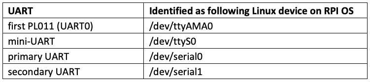
The /dev/serial0 and /dev/serial1 are symbolic links that point to either /dev/ttyS0 or /dev/ttyAMA0. For example, on Raspberry Pi 3/4 /dev/serial0 points to /dev/ttyS0, and /dev/serial1 points to /dev/ttyAMA0. But on Raspberry Pi Zero, /dev/serial0 points to /dev/ttyAMA0, and /dev/serial1 points to /dev/ttyS0. It is possible to know which UART type is primary UART by inspecting the /boot/config.txt file. If in /boot/config.txt file, enable_uart flag is set to 0 by default, mini-UART is the primary UART on that RPi model and if enable_uart flag is set to 1 by default, PL011 is the primary UART on that RPi model.
The mini-UART is linked to the core frequency of the VPU, so that the baud rate (the data-transfer rate over the UART protocol) changes with the core clock frequency. This makes mini-UART unstable. It also lacks parity check, which can lead to data loss or corruption. Therefore, if mini-UART has to be used, its core clock frequency must be fixed.
If mini-UART is set as primary UART, (in /boot/config.txt, enable_uart = 0 is default), the mini-UART can be enabled on serial TTL port of GPIO header and core clock frequency can be set to 250 MHz by setting enable_uart = 1 in the /boot/config.txt. If VPU turbo frequency has to be used as fixed frequency for mini-UART, which is Primary UART in case, force_turbo flag must be set to 1 (force_turbo = 1) in /boot/config.txt file. If mini-UART is set as secondary UART (in /boot/config.txt, enable_uart = 1 is default), the core clock frequency of mini-UART can be set to 250 MHz by setting core_freq flag to 250 (core_freq = 250) in /boot/config.txt file.
This image shows the location of the serial TTL port (the Tx and Rx pins of the primary UART and the hardware serial port on RPi) on RPi’s GPIO header:
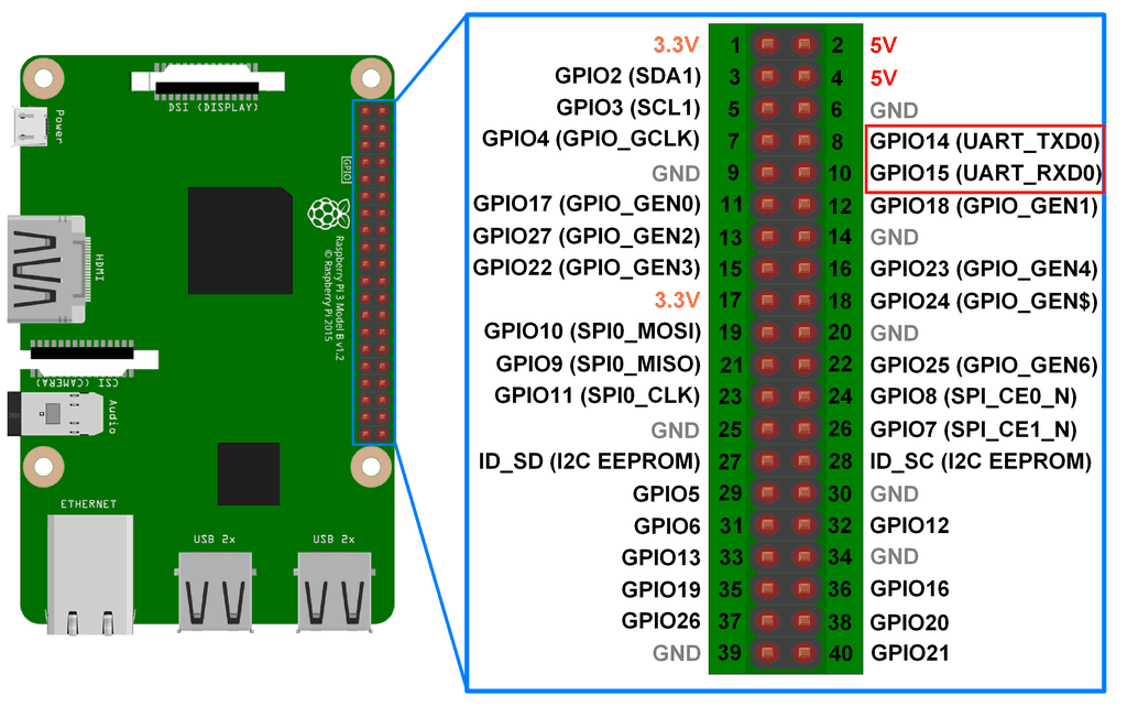
To use this serial TTL port, the serial Linux console on RPi OS must first be disabled since it’s used by default. As both of the UART types are 3.3V compatible, it’s important to use the appropriate serial adaptor for proper serial communication over different interfaces (such as RS-232 or USB).
For example, USB-serial boards should be used for serial communication with a USB interface of other devices. Or, use RS-232-to-TTL-serial-port-converter for interfacing with an RS-232 interface of other devices.
The serial adaptor must also have a 3.3/5V level shifter, so that it can convert the 3.3V TTL logic signals of RPi’s serial TTL port to 5V TTL logic signals (USB) — or other TTL voltage levels (RS-232), according to the interface (USB or RS-232) that the adaptor is designed for use with.
In the user-program (such as Python script), the hardware serial port can be accessed by referencing the respective Linux device. The /dev/serial0 will always point to the primary UART.
The primary UART on serial hardware port can also be accessed by pointing to its UART type. For example, on RPi ¾, mini-UART is the primary UART so /dev/ttyS0 will point to the primary UART on the serial TTL port.
On Raspberry Pi Zero, PL011 is the primary UART so /dev/ttyAMA0 will point to the primary UART on the serial TTL port.
Serial UART communication using RPI’s USB ports
It’s also possible to have serial communication using the UART protocol with the devices connected to the USB ports of RPi. If the device connected to RPI’s USB port identifies as a communications device class (CDC), it’s indicated in the Linux devices as /dev/ttyAMC* (where * is the device number).
For example, Arduino will identify as the CDC device if it’s connected to RPi via a USB-to-USB cable. This is indicated as /dev/ttyAMC0 or /dev/ttyAMC1 if another USB CDC device is already connected to RPi. The serial communication using the UART protocol can be initiated with the device by pointing to it using the respective Linux device (such as /dev/ttyAMC0 for Arduino).
Some devices may not have the hardware USB interface, but a software-only USB stack instead. When such a device is connected to RPI’s USB port, it’s indicated in Linux devices as /dev/ttyUSB* (where * is the device number).
Available serial ports on RPi can be listed by running ls /dev/ command on the shell. If the listed device includes Linux devices, such as /dev/ttyAMC0, /dev/ttyAMC1 etc., these are CDC-class USB devices. If the list includes Linux devices, such as /dev/ttyUSB0, /dev/ttyUSB1, etc., these are USB devices connected via the software-only USB stack.
Serial UART communication using RPI’s Bluetooth & WLAN ports
By default, the secondary UART is connected to a combined WLAN/Bluetooth connecter of Raspberry Pi. To have serial communication over Bluetooth or WLAN using the UART protocol, the Linux device /dev/serial1 can be pointed. Alternatively, /dev/ttyS0 or /dev/ttyAMA0, or whichever is the secondary UART, can be pointed in the user-program (like in a Python script).
Serial UART communication using RPi’s Ethernet port
The secondary UART can be used for serial communication using the UART protocol connected over the Ethernet port. As a secondary UART is by default connected to the Bluetooth/WLAN connector, the Bluetooth connection needs to be disabled by adding this flag in the /boot/config.txt file:
dtoverlay=pi3-disable-bt
Next, the kernel use of the serial port must be disabled in /boot/cmdline.txt file by removing this flag:
console=serial0,115200
Now, the secondary UART can be used for serial UART communication over RPI’s Ethernet port by using tools, such as Point-to-Point Protocol Daemon (pppd).
Hardware serial port vs USB
Most of the embedded electronic modules and sensors use TTL UART ports for interfacing with microcontrollers and embedded computers. Therefore, the hardware serial port (Serial via GPIO Header) is useful for interfacing embedded sensors and modules with the RPi.
General-purpose computing devices can be directly connected to Raspberry Pi via USB-to-USB cables, using RPi’s USB ports. These devices include:
- Laptops, PC, or workstation
- USB-CDC devices
- USB-HID devices
- Software-only USB stack devices
The computing devices can also be interfaced with RPi’s hardware serial port (on a GPIO header) by using a suitable USB-serial adaptor or USB-serial bridge board.
Therefore, a serial hardware port is most useful in embedded applications, and can also be used for interfacing with USB or RS-232 interface devices.
In the next tutorial, we’ll discuss using RPi’s serial hardware port for serial UART communication. We’ll establish a serial read/write communication with a laptop/PC by using RPi’s serial TTL port and a serial-USB adaptor.
Filed Under: Microcontroller Projects, Raspberry pi
Log in to leave a comment:
Lost your password?
Don't have an account? Register here