How generic USB keyboard and mouse are built has been already explained in the Atmega 32u4 based Generic USB Keyboard project and Atmega 32u4 Based USB Mouse project respectively. In this project, another common desktop peripheral – the joystick is designed. A joystick is commonly used for gaming on the desktop computers. This project demonstrates the basic functioning of joystick and how a USB pluggable Joystick can be made using the open source LUFA framework with the Arduino platform. The 8-bit USB AVR – Atmega 32u4 is used as the device controller chip in the project. The project uses AVR based Lightweight USB Framework (LUFA) as the firmware which will be modified to make a custom joystick device.

Fig. 1: Prototype of Arduino Based USB Joystick and Gamepad
The LUFA’s HID device driver class for Joystick is modified to program the project. By using the LUFA firmware, the device driver code to implement USB protocol is not needed to be written explicitly. Modifying the firmware code will be sufficient to implement the project. The project works similar to any generic USB Joystick and instead of using a ball sensor has five button for the following joystick functions – :
• Left Movement or Left Tilt
• Right Movement or Right Tilt
• Forward Movement or Forward Tilt
• Backward Movement or Backward Tilt
• Control Button or Face Button
The project uses tactile switches as the Gamepad buttons, Atmega 32u4 as the controller chip (on board Arduino Pro Micro) and USB cable to connect with the personal computer.
PREREQUISITES
This project is based on Arduino Pro Micro which has the USB AVR – Atmega 32u4 as the sitting MCU. In order to understand this project, one must have basic knowledge of the AVR microcontrollers and the embedded C programming for AVRs. WinAVR Studio is used to write, edit and compile the project code, so closely following the project shall require familiarizing with the above stated IDE as well. Though LUFA framework takes care of implementing the USB protocol and has APIs to abstract the lower level codes, understanding USB protocol is recommended to understand how actually the project is working. In fact, if anyone has already worked on some other microcontroller, it will not be much pain to understand and follow this project as the project code is more or less about getting input from the GPIO pins of AVR MCU and modifying the LUFA device driver to work as generic joystick accordingly.

Fig. 2: Image of Open Game Controllers on Windows
COMPONENTS REQUIRED
1. Arduino Pro Micro
2. Breadboard
3. Connecting wires
4. Push buttons
5. Micro USB cable
6. 10K resistors
SOFTWARE TOOLS REQUIRED
1. WinAVR Studio
2. AVR Dude

Fig. 3: Block Diagram of Arduino Based USB Joystick and Gamepad
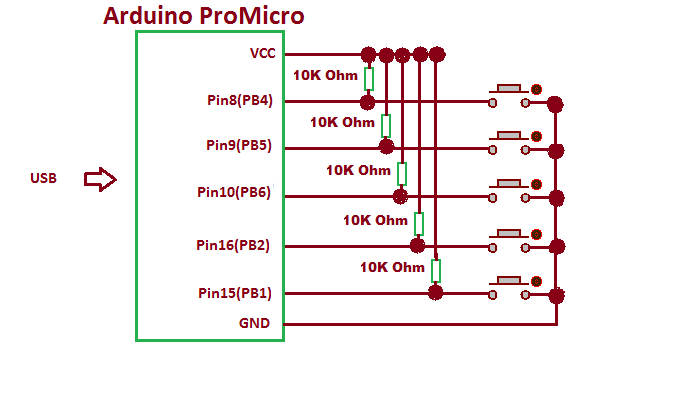
CIRCUIT CONNECTIONS
The project uses Arduino Pro Micro as the USB controller chip. A set of five tactile switches are connected at the port B of the Arduino. The switches are connected at pins 1, 2, 6, 5 and 4 of the port B with functions assigned to them according to the following table – :

Fig. 4: Table listing Arduio pins and respective Keypad functions
The tactile switches are connected between the port and ground. The pins of port B by default are connected to VCC and receive a HIGH logic. Pressing a tactile switch changes the status at the respective pin to LOW by short circuiting to the ground.
The Program code for the project is burnt to the Arduino Pro Micro using AVR Dude. The project device is connected to the USB port of a PC by a USB cable.
HOW THE PROJECT WORKS
In this project the USB protocol is implemented by the LUFA framework. For configuring the controller chip to work as USB Joystick, the HID Class Driver of the LUFA framework for Joystick will be used. The Human Interface Device (HID) class takes care of the transfers between the host device and the human controlled USB peripherals like USB Keyboard, Mouse or Joystick.
When a USB device is attached to the host (PC), the host sends request for configuration details in the form of control transfer. The connected device has to respond with appropriate descriptors to get configured and ready for further operations. Only after configuration, the device can communicate with the host in the form of interrupt, isochronous or bulk transfers for executing the operations for which the device has been made. In case of Joystick, after configuring with the host device, it has to communicate with the host in the form of interrupt transfers for the desired navigational operations. The process of identification and configuration of the device with the host is called enumeration.
A Joystick is HID class USB device and LUFA framework has HID class related module in the LUFA-Source-Folder /LUFA/Drivers/USB/Class/Device folder. Other device class related module are also in the same folder. The LUFA framework has demo projects for different USB device classes in the LUFA-Source-FolderDemosDeviceClassDriver folder. For implementing the project, demo project for Joystick provided in the LUFA framework will be modified and complied. The demo project for Joystick is in the LUFA-Source-FolderDemosDeviceClassDriverJoystick folder. The folder contains Joystick.c file which will be modified to work for our custom joystick device.

Fig. 5: Image showing left tilt of Arduino Based USB Joystick and its effect on cursor
How Joystick.c identifies HID device being Joystick
The Joystick.c uses Joystick_HID_Interface interface in HID_Device_USBTask() function which is being imported from the HIDDeviceClass.c (from LUFA-Source-Folder LUFADriversUSBClassDevice) to configure the device as Joystick. The interface abstracts the low-level descriptor codes and identifies the device as joystick through an InterfaceNumber variable.
Joystick Specific Report Descriptors
Any HID device has to exchange data with the host which should be structured in the form of reports. The report descriptor defines the report structure. A report descriptor contains the information needed by host to determine the data format and how the data should be processed by the host. Therefore, a report descriptor basically structure the data that needs to be exchanged with the host according to the USB protocol.
For working like a joystick, the device needs to send usage report and data (input) report descriptors specific to joystick HID Class to the host. The Usage Report informs the Host about the features or functionality of the USB device whereas the Data Input Report is used to transmit the data to the Host.
From Where Joystick.C gets the USAGE and Data Report Descriptors
In the LUFA framework’s demo project for joystick, descriptor.c file is imported in joystick.c to send the relevant usage and data reports descriptors to the host device. The descriptor.c defines a JoystickReport[] structure which is used in the CALLBACK_HID_Device_CreateHIDReport() function of the joystick.c to generate joystick specific usage and data report descriptors. Inside descriptor.c the JoystickReport[] structure has the values returned by HID_DESCRIPTOR_JOYSTICK () function. The HID_DESCRIPTOR_JOYSTICK () is defined in HIDClassCommon.h (located in LUFA-Source-FolderLUFADriversUSBClassCommon folder). The joystick.c imports joystick.h which imports usb.h. USB.h imports HIDCLass.h. In HIDClass.h is imported HIDClassDevice.h if the USB_CAN_BE_DEVICE is true for the controller chip to being a USB device not the host. The HIDClassDevice.h imports HIDClassCommon.h where the HID device specific descriptor fields have been defined.
USAGE REPORT
HID_DESCRIPTOR_JOYSTICK () returns the following field values of the usage report descriptor, specific to Joystick functioning.

Fig. 6: Table listing field values of usage report descriptor from HID_DESCRIPTOR_JOYSTICK Function
These fields are set to following values in HID_DESCRIPTOR_JOYSTICK ().

Fig. 7: Screenshot of usage report descriptor from HID_DESCRIPTOR_JOYSTICK Function
The Usage or Feature report contains information about the features of the device. In other words, this report informs Host about the features needed in the device. Any typical Joystick consist of two variable axes (X and Y) and two buttons. Though being a rotational sensor device, the movement of joystick is defined through linear axes. A joystick usually works with applications (like desktop games) so physical maximum and physical minimum report items are not part of the usage report of a Joystick. It is the device driver that interprets the normalized values for the linear axes. In LUFA, the device driver uses two variable axes X and Y and utilizes one of the two buttons for Z axis variable. The remaining button is reserved for joystick action.
In the usage report setting the Usage Page report item (defined by macro HID_RI_USAGE_PAGE) to 0x01 configure the device to generic desktop controls. The Usage report item (defined by HID_RI_USAGE) to 0x04 further configure the device to a joystick. The use of these codes for the report items have been taken from the HID Usage Table provided by the USB Implementers Forum. When configured to joystick, the device has a report count of 3 set by HID_RI_REPORT_COUNT macro. So the report contains three words each 8-bit long for X, Y and Z linear variable axes. When button input has to be sent to the host the device is configured to Tablet PC System Controls by setting usage page report item (defined by macro HID_RI_USAGE_PAGE) to 0x09. In this case, the device has a report count of 1 set by HID_RI_REPORT_COUNT macro and only a single 8-bit word for button is transmitted to the host.
The Host can access this report by requesting the device using GET_REPORT request. This report is transmitted using Control Transfer Type of the USB protocol.
DATA REPORT
The Data Input Report contains the data that needs to be transmitted to the Host. It contains data related to the features selected via the Usage Report. The data report for joystick is defined in the joystick.h file in the following manner -:

Fig. 8: Screenshot of data report for joystick
The data report for joystick consists of 4 bytes of which first three bytes are signed 8-bit integers and are used to transmit X, Y and Z variable axes. The last byte is an unsigned integer used to transmit the status of button mask to the host. Not all bits of the button byte are used. In fact, the unused bits of the button byte are padded with zero.
HOW THE DEVICE WORKS
The AVR microcontroller is programmed to work with the tactile switches to get the joystick inputs. The main() function and the CALLBACK_HID_Device_CreateHIDReport() function of the joystick.c are modified to customize the device for working with tactile switches as source for reading desired joystick inputs. Check out the program code to see the modifications implemented for this custom joystick device.
PROGRAMMING GUIDE
For building the project download the LUFA framework from the github.com. The demo project provided with the LUFA framework is modified to make this custom joystick device. In the extracted LUFA zip file, open Demos/Device/ClassDriver/Joystick folder. The folder has the following files and folders.

Fig. 9: Screenshot of LUFA Library Folder on Windows
Of these, Joystick.h, Joystick.c and Makefile needs to be modified for this project. The modified files (provided at the bottom of the article in zip format) can also be downloaded from the engineersgarage and replaced with the original files. Either open the files in WinAVR Studio or Notepad++ and modify original files or replace files with the already modified one. The modified or replaced Joystick.c needs to be compiled from within the LUFA’s Source folder to get the object code.
Modifying Joystick.h
The Joystick.h library file is imported in the Joystick.c file and includes a set of additional libraries and defines the constants and functions for the joystick device. These include the additional libraries for the joystick itself, button and LEDs which should be commented out as the project is not using these HID features. So open Joystick.h and make the following changes – :
• Comment the #include library statements for Joystick.h, LEDS.h, and Buttons.h ( We are commenting these libraries as we are not using any buttons board and LED board and the Joystick.h does not need to import itself)
Save the file with changes.
Modifying Joystick.C file
Again in the Joystick.c, the code sections for Joystick, button board and LEDs need to be commented out. So open Joystick.c and make the following changes – :
• In the main loop, comment the LEDs_SetAllLEDs()
• In SetupHardware() function, comment the Joystick_Init(), LEDs_Init(), Buttons_Init()
• In EVENT_USB_Device_Connect() function, comment the LEDs_SetAllLEDs()
• In EVENT_USB_Device_Disconnect() function, comment LEDs_SetAllLEDs()
• In EVENT_USB_Device_ConfigurationChanged() function, comment the LEDs_SetAllLEDs()
In Joystick.c the main() function executes the functioning of the Joystick. Inside the main function Port B where the tactile switches have been connected needs to be defined as input and all the pins of port B has to be raised to HIGH logic by default as the microcontroller will need to detect LOW logic for input from tactile switches. So add the following statements in the beginning of main() function – :
Inside the infinite for loop the HID_Device_USBTask() function is called where Joystick_HID_Interface interface is passed as parameter. The interface identifies the device as Joystick and abstracts the low level program code specific to joystick HID class. The function is coming from the HIDClassDevice.c module (located in LUFA/Drivers/USB/Class/Device/HIDClassDevice.c) and is used for general management task for a given HID class interface, required for the correct operation of the interface. It should be called in the main program loop, before the master USB management task USB_USBTask(). The USB_USBTask() is the main USB management task. The USB driver requires this task to be executed continuously when the USB system is active (device attached in host mode, or attached to a host in device mode) in order to manage USB communications. The function is defined in USBTask.c (Located in LUFA-Source-FolderLUFADriversUSBCore folder).
For creating Joystick Data report CALLBACK_HID_Device_CreateHIDReport() needs to be modified. The default file has the function body to detect rotational sensor’s movement.

Fig. 10: Screenshot of CALLBACK_HID_Device_CreateHIDReport Function in LUFA Library
This project is using tactile switches to get joystick specific user inputs. Therefore, LOW bit at each button is detected and the corresponding report item is altered in data report and transmitted to the host. So replace the body of the function with the following code -:
In the body _BV() function is used to map the respective bit as a byte with only the respective bit changed in the returned byte. When a positive 100 value is passed to the X linear variable axis, the game object moves in the right direction by 100 pixels while when negative 100 value is passed to the X linear variable axis, the game object moves in the left direction by 100 pixels. When a positive 100 value is passed to the Y linear variable axis, the game object moves in the upward direction by 100 pixels while when negative 100 value is passed to the Y linear variable axis, the game object moves in the downward direction by 100 pixels. The button press is simulated by setting the LSB of the button byte to 0.
Save the file and create Make file for the project.
Modifying Make File
In the Joystick folder there is a make file that needs to be edited. The file can be edited using Notepad++. The following information needs to be edited – :
• MCU = atmega32u4
• ARCH = AVR8
• BOARD = LEONARDO
• F_CPU = 16000000
Save the file and exit. Now all the files are edited completely for the basic HID Joystick application.
Compiling Joystick.c
For compiling the source code, WinAVR Programmers Notepad or Arduino IDE can be used. Open the modified Joystick.c file and compile the code.
BURNING HEX CODE
The hex file is generated on compiling the Joystick.c file. For burning the object code to microcontroller open the Command Prompt, change the current directory to the directory containing the Hex file. This can be done using command: CD <address of the directory>. Now reset the Arduino and instantly run the command: : avrdude -v -p atmega32u4 -c avr109 -P COM20 -b 57600 -D -Uflash:w:Joystick.hex:i after replacing the COM Port with the recognized one.
If the uploading process is successful, the Arduino will be shown as HID Joystick in the Device Manager. There is no need of installing any driver in the computer as Generic HID Joystick is used for the project implementation. Launch any desktop game and use the buttons to test the project device working like a generic USB Joystick.
In the next project – Atmega 32u4 Based Volume Control application, media controller application interface of LUFA framework will be revisited with the project implementing volume control based on touch.
Project Source Code
###
LUFA Library Copyright (C) Dean Camera, 2015. dean [at] fourwalledcubicle [dot] com www.lufa-lib.org */ /* Copyright 2015 Dean Camera (dean [at] fourwalledcubicle [dot] com) Permission to use, copy, modify, distribute, and sell this software and its documentation for any purpose is hereby granted without fee, provided that the above copyright notice appear in all copies and that both that the copyright notice and this permission notice and warranty disclaimer appear in supporting documentation, and that the name of the author not be used in advertising or publicity pertaining to distribution of the software without specific, written prior permission. The author disclaims all warranties with regard to this software, including all implied warranties of merchantability and fitness. In no event shall the author be liable for any special, indirect or consequential damages or any damages whatsoever resulting from loss of use, data or profits, whether in an action of contract, negligence or other tortious action, arising out of or in connection with the use or performance of this software. */ /** file * * Main source file for the Joystick demo. This file contains the main tasks of * the demo and is responsible for the initial application hardware configuration. */ #include "Joystick.h" /** Buffer to hold the previously generated HID report, for comparison purposes inside the HID class driver. */ static uint8_t PrevJoystickHIDReportBuffer[sizeof(USB_JoystickReport_Data_t)]; /** LUFA HID Class driver interface configuration and state information. This structure is * passed to all HID Class driver functions, so that multiple instances of the same class * within a device can be differentiated from one another. */ USB_ClassInfo_HID_Device_t Joystick_HID_Interface = { .Config = { .InterfaceNumber = INTERFACE_ID_Joystick, .ReportINEndpoint = { .Address = JOYSTICK_EPADDR, .Size = JOYSTICK_EPSIZE, .Banks = 1, }, .PrevReportINBuffer = PrevJoystickHIDReportBuffer, .PrevReportINBufferSize = sizeof(PrevJoystickHIDReportBuffer), }, }; /** Main program entry point. This routine contains the overall program flow, including initial * setup of all components and the main program loop. */ int main(void) { SetupHardware(); DDRB = 0x00; PORTB = 0xff; //LEDs_SetAllLEDs(LEDMASK_USB_NOTREADY); GlobalInterruptEnable(); for (;;) { HID_Device_USBTask(&Joystick_HID_Interface); USB_USBTask(); } } /** Configures the board hardware and chip peripherals for the demo's functionality. */ void SetupHardware(void) { #if (ARCH == ARCH_AVR8) /* Disable watchdog if enabled by bootloader/fuses */ MCUSR &= ~(1 << WDRF); wdt_disable(); /* Disable clock division */ clock_prescale_set(clock_div_1); #elif (ARCH == ARCH_XMEGA) /* Start the PLL to multiply the 2MHz RC oscillator to 32MHz and switch the CPU core to run from it */ XMEGACLK_StartPLL(CLOCK_SRC_INT_RC2MHZ, 2000000, F_CPU); XMEGACLK_SetCPUClockSource(CLOCK_SRC_PLL); /* Start the 32MHz internal RC oscillator and start the DFLL to increase it to 48MHz using the USB SOF as a reference */ XMEGACLK_StartInternalOscillator(CLOCK_SRC_INT_RC32MHZ); XMEGACLK_StartDFLL(CLOCK_SRC_INT_RC32MHZ, DFLL_REF_INT_USBSOF, F_USB); PMIC.CTRL = PMIC_LOLVLEN_bm | PMIC_MEDLVLEN_bm | PMIC_HILVLEN_bm; #endif /* Hardware Initialization */ //Joystick_Init(); //LEDs_Init(); //Buttons_Init(); USB_Init(); } /** Event handler for the library USB Connection event. */ void EVENT_USB_Device_Connect(void) { //LEDs_SetAllLEDs(LEDMASK_USB_ENUMERATING); } /** Event handler for the library USB Disconnection event. */ void EVENT_USB_Device_Disconnect(void) { //LEDs_SetAllLEDs(LEDMASK_USB_NOTREADY); } /** Event handler for the library USB Configuration Changed event. */ void EVENT_USB_Device_ConfigurationChanged(void) { bool ConfigSuccess = true; ConfigSuccess &= HID_Device_ConfigureEndpoints(&Joystick_HID_Interface); USB_Device_EnableSOFEvents(); //LEDs_SetAllLEDs(ConfigSuccess ? LEDMASK_USB_READY : LEDMASK_USB_ERROR); } /** Event handler for the library USB Control Request reception event. */ void EVENT_USB_Device_ControlRequest(void) { HID_Device_ProcessControlRequest(&Joystick_HID_Interface); } /** Event handler for the USB device Start Of Frame event. */ void EVENT_USB_Device_StartOfFrame(void) { HID_Device_MillisecondElapsed(&Joystick_HID_Interface); } /** HID class driver callback function for the creation of HID reports to the host. * * param[in] HIDInterfaceInfo Pointer to the HID class interface configuration structure being referenced * param[in,out] ReportID Report ID requested by the host if non-zero, otherwise callback should set to the generated report ID * param[in] ReportType Type of the report to create, either HID_REPORT_ITEM_In or HID_REPORT_ITEM_Feature * param[out] ReportData Pointer to a buffer where the created report should be stored * param[out] ReportSize Number of bytes written in the report (or zero if no report is to be sent) * * return Boolean c true to force the sending of the report, c false to let the library determine if it needs to be sent */ bool CALLBACK_HID_Device_CreateHIDReport(USB_ClassInfo_HID_Device_t* const HIDInterfaceInfo, uint8_t* const ReportID, const uint8_t ReportType, void* ReportData, uint16_t* const ReportSize) { USB_JoystickReport_Data_t* JoystickReport = (USB_JoystickReport_Data_t*)ReportData; if(!(PINB & _BV(PB4))) { // push button to move forward JoystickReport->Y = +100; } if(!(PINB& _BV(PB5))) { // push button to move backward JoystickReport->Y = -100; } if(!(PINB & _BV(PB6))) { // push button to move right JoystickReport->X = +100; } if(!(PINB & _BV(PB2))) { // push button to move left JoystickReport->X = -100; } if(!(PINB & _BV(PB1))) { // button press JoystickReport->Button |= (1 << 0); } *ReportSize = sizeof(USB_JoystickReport_Data_t); return false; } /** HID class driver callback function for the processing of HID reports from the host. * * param[in] HIDInterfaceInfo Pointer to the HID class interface configuration structure being referenced * param[in] ReportID Report ID of the received report from the host * param[in] ReportType The type of report that the host has sent, either HID_REPORT_ITEM_Out or HID_REPORT_ITEM_Feature * param[in] ReportData Pointer to a buffer where the received report has been stored * param[in] ReportSize Size in bytes of the received HID report */ void CALLBACK_HID_Device_ProcessHIDReport(USB_ClassInfo_HID_Device_t* const HIDInterfaceInfo, const uint8_t ReportID, const uint8_t ReportType, const void* ReportData, const uint16_t ReportSize) { // Unused (but mandatory for the HID class driver) in this demo, since there are no Host->Device reports }###
Circuit Diagrams
Project Datasheet
Project Video
Filed Under: Electronic Projects
Filed Under: Electronic Projects

Questions related to this article?
👉Ask and discuss on Electro-Tech-Online.com and EDAboard.com forums.
Tell Us What You Think!!
You must be logged in to post a comment.