Automatic fan speed regulator automatically regulates the speed of the fan according to the temperature inside the room. Due to sudden changes in atmosphere because of pollution, we feel hot and after some time we feel cold. And we have to regulate the speed of fan. Hence to solve this problem we have described this simple circuit.
This Automatic fan speed regulator circuit is very useful in night especially in summers. In summers initially at night temperature is high and as time progresses temperature stops dropping. When you fall asleep metabolic rate of your body decreases and we started felling cold and this make break your sleep as you have to regulate the speed of fan. So just connect the outputs to the regulator of your fan through this circuit and it will automatically change the fan speed and you can sleep comfortably.
[[wysiwyg_imageupload:10872:]]
Fig. 1: Prototype of Automatic Fan Speed Regulator Circuit on Breadboard
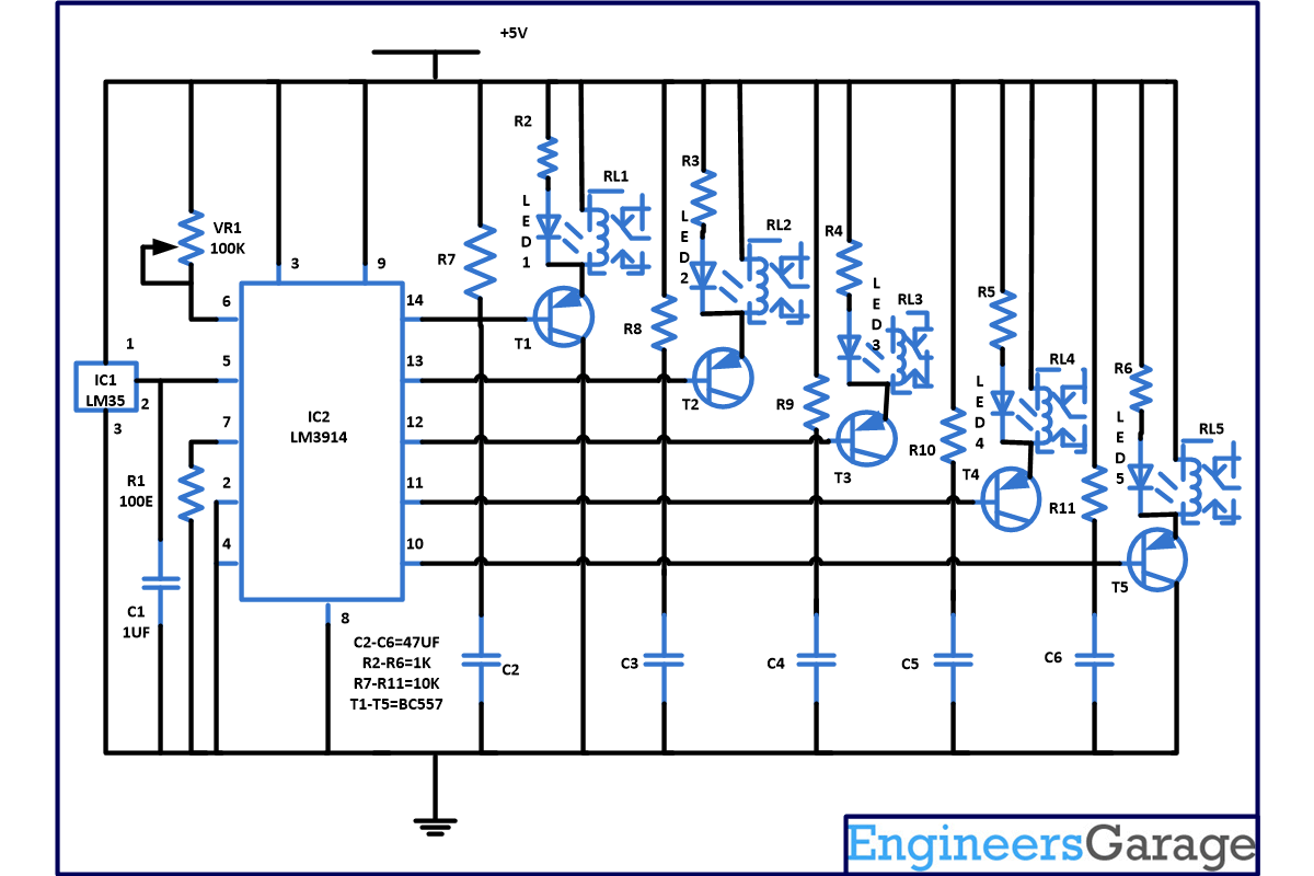
This circuit is based on two IC LM35 and LM3914 with few more components.
And LM35 is a precision integrated circuit temperature measurement IC and its output voltage is linearly proportional to centigrade temperature. LM35 detects the surrounding temperature and according to reference value set it will give you the output. When output voltage is multiplied by 100 it will give you the temperature sensed in degrees. So you can easily set your reference voltage. Pin configuration of LM35 IC is shown below.

Fig. 2: Pin Configuration of LM35 IC
LM3914 is a monolithic integrated circuit which senses the analog voltage and derives 10 LED’s providing a linear analog display.
Advantage of IC LM3914-
1. In this user can easily select the dot or bar graph display just by changing a single pin.
2. This IC can drive LED’s, LCD or vacuum fluorescent display.
3. You can cascade more IC’s up to 100 steps.
4. This IC can also work on 3V power supply.
5. In this we do not require resistor with the LED’s because current drive to LED’s is regulated and programmed.
6. It will support wide temperature range from 0 degree to +70 degree Celsius.
Working of the automatic fan speed regulator circuit:
Mostly fan regular has 5 speed controls so in our circuit out of 10 we are utilizing 5 outputs. For calibrating the circuit use VR1 and set the reference voltage of approx .21V. So when temperature reaches more than 21degree Celsius sensed by the sensor LM35, pin 5 of IC2 goes high this will make pin 14 of IC2 also high, which in turn on the transistor T1 and relay get energize. Now your fan start rotating in 1 position and when temperature in room is below 21 degree Celsius relay get de energize as the reference voltage is more than the room temperature and fan stop rotating.
Now when voltage reaches 25 degree Celsius as sensed by sensor it will again provide a high at pin 13 of IC2 and relay 2 start conducting with the help of transistor T2 and fan speed also increases to second position . Similarly when temperature reaches to 29 degree Celsius relay 3 conducts and when temperature reaches 33 degree Celsius and 36 degree Celsius, relay 4 and relay 5 conducts.
And when temperature inside the room decreases than relay start de energise to reduce the speed of the fan.
Circuit Diagrams
Project Components
Project Video
Filed Under: Electronic Projects
Filed Under: Electronic Projects


Questions related to this article?
👉Ask and discuss on Electro-Tech-Online.com and EDAboard.com forums.
Tell Us What You Think!!
You must be logged in to post a comment.