In this tutorial, an autonomous fire extinguisher robot is designed. The robot has fire sensors interfaced in its control circuitry which senses the presence and intensity of fire and take the responsive action accordingly. The robot is designed to detect intensity of fire and operate first at place where the intensity of fire is more. It is also an automatic robot as it does not need to be operated from any remote control. One only needs to deploy the robot in a fire prone zone and the robot will automatically initiate action once it detects a fire breakout. This Robot finds its applications in Rescue operations during fire accidents where the possibility for service men to enter the fire prone areas is very less.
The control circuitry of the robot is built on Arduino UNO. There are three fire sensors interfaced in the control circuitry in the forward, left and right side of the robot. A motor fan is attached on the robot which will actually simulate the functioning of a water pump. This is a prototype model. In a production model, a motor pump should be attached in place of the fan. Apart from the component’s interfacing in the circuit, the main significance is of the Arduino sketch running on the controller circuit. It is the Arduino sketch which provides the software intelligence to sense fire intensity using fire sensors, move robot in the direction where fire intensity is more and increase or decrease speed of motor pump. The Arduino sketch is written and compiled using Arduino IDE.

Fig. 1: Prototype of Arduino based Fire Fighting Robot
Components Required –

Fig. 2: List of components required for Arduino based Fire Fighting Robot
Block Diagram –

Fig. 3: Block Diagram of Arduino based Fire Fighting Robot
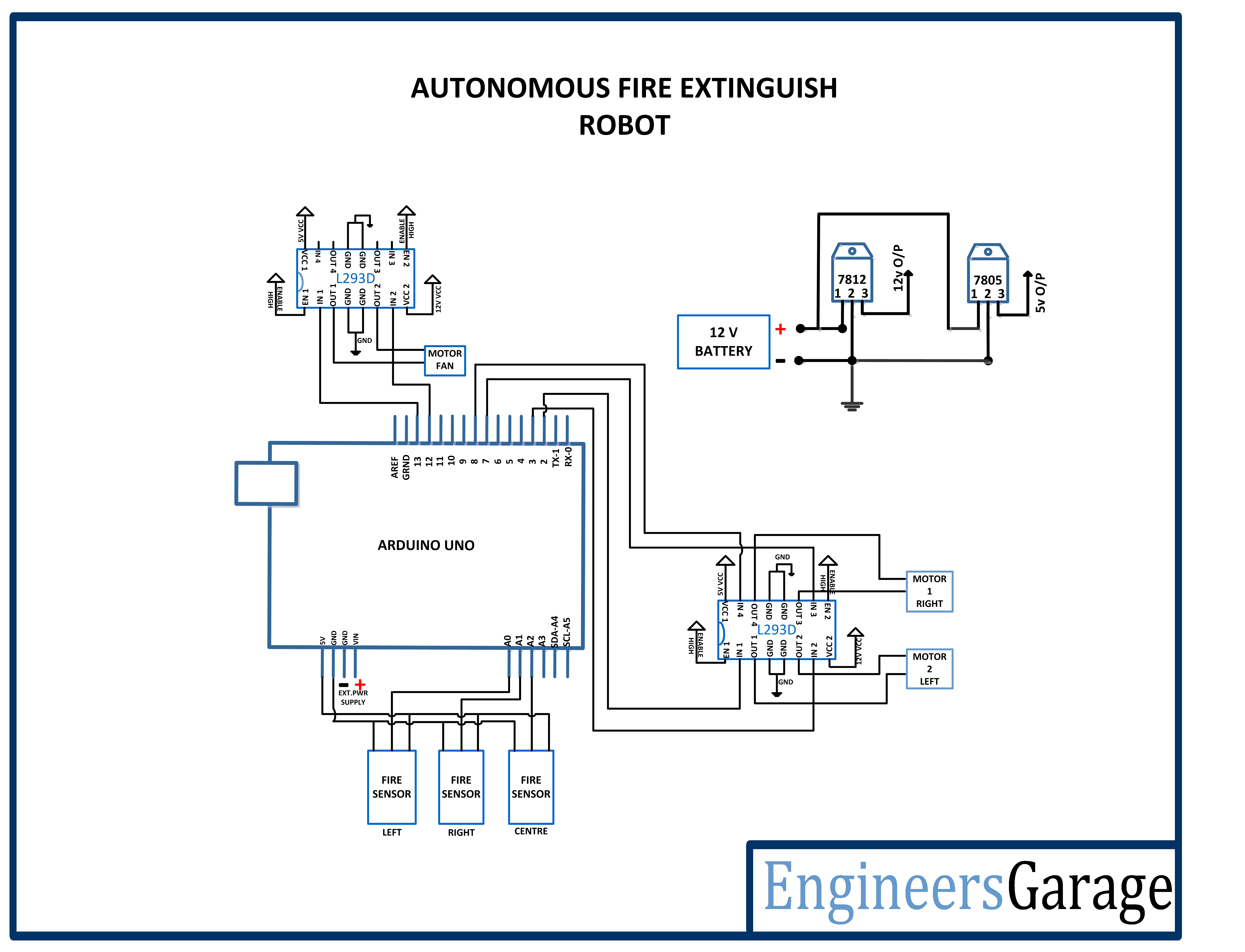
Circuit Connections –
The control circuitry is built around Arduino UNO. The fire sensors and motor driver ICs are interfaced to the controller board.

Fig. 4: Image showing Arduino based Control Circuit Mounted at the top of the Fire Fighting Robot
The circuit is made by assembling the following components together –
Power Supply – In the circuit, Arduino board and fire sensors need a 5V regulated DC for their operation while the motor driver ICs needs 12V DC. A 12V NIMH battery is used as the primary source of power. The supply from the battery is regulated to 5V and 12V using 7805 and 7812 ICs. The pin 1 of both the voltage regulator ICs is connected to the anode of the battery and pin 2 of both ICs is connected to ground.
The respective voltage outputs are drawn from pin 3 of the respective voltage regulator ICs. An LED along with a 10K Ω pull-up resistor is also connected between common ground and output pin to get a visual hint of supply continuity. Despite using 12V battery, 7812 is used to provide a regulated and stable supply to the motor driver IC.
Arduino UNO – Arduino UNO is one of the most popular prototyping boards. It is used frequently in robotic applications as it is small in size and packed with rich features. The board comes with built-in arduino boot loader. It is an Atmega 328 based controller board which has 14 GPIO pins, 6 PWM pins, 6 Analog inputs and on board UART, SPI and TWI interfaces. In this project, three analog input pins of the board are utilized to connect fire sensors and 6 GPIO pins are used to interface L293D motor driver ICs.
L293D DC Motor Driver IC – The L293D is a dual H-bridge motor driver integrated circuit (IC). The Motor drivers act as current amplifiers since they take a low-current control signal and provide a higher-current signal. This higher current signal is used to drive the motors. It has 16 pins with following pin configuration:

Fig. 5: Table listing pin configuration of L293D Motor Driver IC
For robot’s motion, there are two DC motors used. The DC motors are interfaced between pins 3 and 6 and pins 14 and 11 of one of the motor driver IC.
The L293D IC controls the DC Motors according to the following truth tables:

Fig. 6: Truth Tableof L293D Motor Driver IC
The pin 4, 5, 13 and 12 of the L293D controlling DC motors for robot’s navigation are grounded while pins 1, 16 and 9 are connected to 5V DC and pin 8 is connected to 12V DC. The pins 15, 2, 7 and 10 of this motor driver IC are connected to pins 8, 2, 3 and 7 of the Arduino board. The DC motor attached to right wheel is connected to pins 11 and 14 while motor attached to left wheel is connected to pins 3 and 6 of the motor driver IC.
Another L293D IC is used to control a DC motor used for running a fan or pump. The pin 4, 5, 13 and 12 of this L293D IC are grounded while pins 1, 16 and 9 are connected to 5V DC and pin 8 is connected to 12V DC. The motor fan is connected between pins 3 and 6 of this IC and the pins 2 and 7 of this motor driver IC are connected to pins 13 and 12 of the Arduino board.
Geared DC Motors – In this robot, 12V geared DC motors are attached to the wheels. Geared DC motors are available with wide range of RPM and Torque, which allow a robot to move based on the control signal it receives from the motor driver IC.
Fire Sensors – A Fire Detection Sensor is sensitive to the flame but also can detect ordinary light. It is usually used as a fire alarm. It detects a flame or a light source of a wavelength in the range of 760 nm to 1100 nm. The detection point is about 60 degrees, particularly sensitive to the flame spectrum. It can detect the fire from a distance about 1 M to 2 M. IR receivers are used as fire detection sensors in the circuit.
We have designed our own analog fire sensor where it makes use of the IR receiver. The IR sensors are connected in a voltage divider circuit and interfaced to the analog input pins of the Arduino. The output of the voltage divider circuits is connected to pins A0, A1 and A2 of the controller board.

Fig. 7: Typical Image of IR Receiver

Fig. 8: Circuit Diagram of IR Receiver used as Fire Detection Sensor in Voltage Divider Configuration
How the circuit works –
The working of the circuit is simple and straightforward. The IR sensors used for fire detection are connected in voltage divider configuration with the analog input pins of the controller. The resistance of the sensor changes when light from the flames falls on it. Due to change in resistance of the IR receiver, the analog voltage also varies between ground to VCC. The analog voltage is read from the analog input pin of the controller and converted to a digitized reading using inbuilt ADC channel. The Arduino UNO has 10-bit ADC channels, so the digitized reading ranges from 0 to 1023. The sensors are calibrated to detected fire from a distance of 1 Metre. Appropriate reading corresponding to the calibration point is set as the threshold in the program code. The same calibration is done for all the three sensors.
The controller is programmed to move the robot in forward direction when the front sensor detects fire and move in the left or right direction when the fire is detected by the left or right sensor respectively. As the robot moves towards the fire spot, the fan or water pump attached to the robot is also activated. The robot can be moved forward, backward, left or right by implementing the following input logic at the motor driver pins –

Fig. 9: Logic Table of L293D Motor Driver IC for Arduino Robot
The Arduino sketch changes the digital output at the input pins of the motor driver IC to control the motion of the robot. In this project, the robot is designed to move autonomously. It turns left and moves forward to reach an appropriate spot if fire is sensed by the left sensor. It turns right and moves forward to reach an appropriate spot if fire is sensed by the right sensor. It moves forward or backward until it reaches an appropriate spot if fire is detected by the front sensor.
The threshold value of the sensor is calibrated to 400. As the robot moves towards fire, the sensor value also increases. The robot stop at a spot and initiate responsive action as the sensor reading reaches a value of 900. The robot moves first in a direction where the intensity of fire is most and after extinguishing fire, it turns in the opposite direction. Like if it had turned left, after extinguishing fire, it will turn right and vice versa.

Fig. 10: Flowchart for Arduino Robot’s Fire Fighting Algorithm
As a responsive action, a fan is started which can blow carbon dioxide at the fire spot. For activating the fan mounted on the robot, the motor attached to fan can be either rotated clock-wise or anti-clockwise by sending Low and High logic or High and low logic at the pins 2 and 7 of the other motor driver IC. The fan can be rotated either way. In a production model, the fan will be actually used to blow carbon dioxide at the fire spot. Instead of the motor fan, even a water pump can be attached in the robot by interfacing it through an additional circuitry.
The robot designed in this tutorial is a prototype. A production robot should have a fireproof body and should have control circuitry protected in a fireproof casing. A production robot may have specifically designed robotic body which can move around and enter any place with ease. It can have a larger battery pack and a powerful water pump or motor fan mounted on it.
Programming Guide –
The Arduino Sketch is responsible for reading data from the IR receivers as a digital value and compare values read from the sensors with a calibrated threshold. If the sensor’s value exceeds the threshold value, the program code turns the robot in the direction of the sensor and starts the fan or water pump. The code starts with the declaration of constants and variables representing motor driver IC connections and connections of the fire detection sensors.
The following block of code in void loop() function represents reading the analog values from the fire sensors on left, right and from the centre (front) sensor.
left_reading = analogRead(left);
Serial.print(“left = “);
Serial.println(left_reading);
delay(500);
right_reading = analogRead(right);
Serial.print(“right = “);
Serial.println(right_reading);
delay(500);
centre_reading = analogRead(centre);
Serial.print(“centre = “);
Serial.println(centre_reading);
delay(500);
The following block of code represents when the fire is detected on the left side. As the value of analog sensor mounted on the left side goes beyond 400 (calibrated threshold), the robot turns left and moves forward till it reaches near fire spot. As the robot will move towards the fire, the sensor value will keep increasing. As the sensor value goes above 900 the robot stops and the motor fan or water pump is turned ON to extinguish the fire. Once the center value of sensor goes down 400 (i.e. when the fire is extinguished) the robot takes right.
if(left_reading > 300)
{
turnleft();
Serial.println(“……………..Left”);
delay(1300);
moveforward();
Serial.println(“……………..Forward”);
delay(1100);
if(analogRead(centre) > 991)
{
robostop();
Serial.println(“……………..Stop”);
digitalWrite(12, HIGH);
digitalWrite(13, LOW);
delay(5000);
digitalWrite(12, LOW);
digitalWrite(13, LOW);
}
delay(1100);
turnright();
Serial.println(“……………..Right”);
delay(1300);
robostop();
}
The similar code is written for the right sensor and if the fire is detected from the front, the robot just stops and extinguishes the fire. This completes the Arduino sketch for the autonomous fire fighting the robot.
Project Source Code
###
//Program to #define LM1 2 //define the pin numbers for motor #define LM2 3 #define RM1 7 #define RM2 8 int left = 0; int right = 1; int centre = 2; int left_reading = 0; int right_reading = 0; int centre_reading = 0; void moveforward(); void movebackward(); void turnleft(); void turnright(); void robostop(); void setup() //setup function to define the pin Mode whether as input or output for motors and sensors { Serial.begin(9600); pinMode(LM1, OUTPUT); pinMode(LM2, OUTPUT); pinMode(RM1, OUTPUT); pinMode(RM2, OUTPUT); pinMode(13, OUTPUT); // define the pin and mode for motor with fan pinMode(12, OUTPUT); } void loop() //infinite loop function { // Read the sensor value connected to the analog pins left_reading = analogRead(left); // A0 pin Serial.print("left = "); Serial.println(left_reading); delay(500); right_reading = analogRead(right); //A1 pin Serial.print("right = "); Serial.println(right_reading); delay(500); centre_reading = analogRead(centre); //A2 pin Serial.print("centre = "); Serial.println(centre_reading); delay(500); if(left_reading > 300) //if condition to check reading of left sensor is high { turnleft(); Serial.println(".................Left"); delay(1300); moveforward(); //if high make the robot move forward Serial.println(".................Forward"); if(analogRead(centre) > 991) //by reaching near fire sensor value goes high { robostop(); Serial.println(".................Stop"); digitalWrite(12, HIGH); digitalWrite(13, LOW); delay(5000); digitalWrite(12, LOW); digitalWrite(13, LOW); } delay(1100); turnright(); // After extinguish the fire turn the robot Serial.println(".................Right"); delay(1300); robostop(); } if(right_reading > 400) { turnright(); Serial.println(".................Right"); delay(1300); moveforward(); Serial.println("................Forward"); if(analogRead(centre) > 991) { robostop(); Serial.println("................Stop"); digitalWrite(12, HIGH); digitalWrite(13, LOW); delay(5000); digitalWrite(12, LOW); digitalWrite(13, LOW); } delay(1100); turnleft(); Serial.println(".................Left"); delay(1300); robostop(); } if(centre_reading > 400) { moveforward(); Serial.println(".................Forward"); if(analogRead(centre) > 991) { robostop(); Serial.println(".................Stop"); digitalWrite(12, HIGH); digitalWrite(13, HIGH); delay(5000); digitalWrite(12, LOW); digitalWrite(13, LOW); } } } #if 1 void moveforward() //function definition to move the robot forward { digitalWrite(LM1, HIGH); digitalWrite(LM2, LOW); digitalWrite(RM1, HIGH); digitalWrite(RM2, LOW); } void movebackward() //function definition to move the robot backward { digitalWrite(LM1, LOW); digitalWrite(LM2, HIGH); digitalWrite(RM1, LOW); digitalWrite(RM2, HIGH); } void turnleft() //function definition to turn the robot left { digitalWrite(LM1, HIGH); digitalWrite(LM2, LOW); digitalWrite(RM1, LOW); digitalWrite(RM2, LOW); } void turnright() //function definition to turn the robot right { digitalWrite(LM1, LOW); digitalWrite(LM2, LOW); digitalWrite(RM1, HIGH); digitalWrite(RM2, LOW); } void robostop() //function definition to stop the robot { digitalWrite(LM1, LOW); digitalWrite(LM2, LOW); digitalWrite(RM1, LOW); digitalWrite(RM2, LOW); } #endif###
Circuit Diagrams
Project Video
Filed Under: Electronic Projects
Filed Under: Electronic Projects

Questions related to this article?
👉Ask and discuss on EDAboard.com and Electro-Tech-Online.com forums.
Tell Us What You Think!!
You must be logged in to post a comment.