Engineers Garage

  • Electronic Projects & Tutorials
    • Electronic Projects
      • Arduino Projects
      • AVR
      • Raspberry pi
      • ESP8266
      • BeagleBone
      • 8051 Microcontroller
      • ARM
      • PIC Microcontroller
      • STM32
    • Tutorials
      • Sensor Series
      • 3D Printing
      • AI
      • ARDUINO Compatible Coding
      • Audio Electronics
      • Battery Management
      • Beginners Electronics Series
      • Brainwave
      • Digital electronics (DE)
      • Electric Vehicles
      • EMI/EMC/RFI
      • EVs
      • Hardware Filters
      • IoT tutorials
      • LoRa/LoRaWAN
      • Power Tutorials
      • Protocol
      • Python
      • RPI Python Programming
      • Sensors
      • USB
      • Thermal management
      • Verilog
      • VHDL
    • Circuit Design
    • Project Videos
    • Components
  • Articles
    • Tech Articles
    • Insight
    • Invention Stories
    • How to
    • What Is
  • News
    • Electronic Product News
    • Business News
    • Company/Start-up News
    • DIY Reviews
    • Guest Post
  • Forums
    • EDABoard.com
    • Electro-Tech-Online
    • EG Forum Archive
  • DigiKey Store
    • Cables, Wires
    • Connectors, Interconnect
    • Discrete
    • Electromechanical
    • Embedded Computers
    • Enclosures, Hardware, Office
    • Integrated Circuits (ICs)
    • Isolators
    • LED/Optoelectronics
    • Passive
    • Power, Circuit Protection
    • Programmers
    • RF, Wireless
    • Semiconductors
    • Sensors, Transducers
    • Test Products
    • Tools
  • Learn
    • eBooks/Tech Tips
    • Design Guides
    • Learning Center
    • Tech Toolboxes
    • Webinars & Digital Events
  • Resources
    • Digital Issues
    • EE Training Days
    • LEAP Awards
    • Podcasts
    • Webinars / Digital Events
    • White Papers
    • Engineering Diversity & Inclusion
  • Guest Post Guidelines
  • Advertise
  • Subscribe

Toggle/Blink led on specific delay with pic microcontroller using timers: MPLABX and xc8 compiler

By EG Projects August 7, 2019

This is advance tutorial on blink/toggle led with pic microcontroller using pic microcontroller timers. I am going to teach you how to toggle led on specific delay time generated using timers of pic micrococntroller. This tutorial is not limited to only toggling led, it can be utilized at many other places. Like generating an event after specific delay, triggering a signal after specific time, reading data on known intervals, outputting data after desired time delay, pwm(pulse width modulation) signal generation, servo motor control etc. The algorithm discussed in the tutorial/post/project can also be used to output a desired frequency signal, by converting time domain signal in to frequency domain. 

In the previous tutorial we discussed about how to generate a specific delay using internal timers of pic microcontroller. We also derived and discussed the formula for calculating the output signal period. We also discussed the terms related with the time/frequency formula derivation, such as Tick_counter frequency, Timer Count etc. This tutorial is in chain with the previous one the code used below in inherited from the previous tutorial. I recommend to first go through the previous simple tutorial. You can easily understand the code below if you take the tutorial

  • Specific Delay generation using internal timers of pic microcontroller  

Now you have taken the above tutorial its time to start with this tutorial. Suppose we want to toggle an led, generate and event or read data after 10 ms with 20 Mhz clock source. I selected the prescaller to be 1:4. For this we have to calculate the “Timer Count” value. Lets start deriving the “Timer Count”. The formula is given below.

Specific delay formula for Pic Microcontroller’s

10 ms = Timer Count * ( 4 / (20M hz/ 4) )
10 ms = Timer Count * ( 4 / 5 Mhz)
10 ms * 5 M hz = Timer Count * 4
50 k = Timer Count * 4
50000 / 4 = Timer Count
Timer Count = 12500 (Hex 0x30D4)
Pic microcontroller time delay formula

Pic microcontroller time delay formula

Timer register value comes out to be 12500(0x30D4) for the above given data. 0x30D4 is a 16-bit value which we have to load in the timer TMR register. TMR register is devided in to two 8-bit registers TMRxH and TMRxL register. TMRxH is timer high byte load the high byte in it, in our case its 30. TMRxL is timer low byte timer low byte is loaded in it, in our case its D4. x denotes the timer we are going to use. Pic base series microcontrollers generally have 3 timers Timer-1, Timer-2 and Timer-3. So if we are using Timer-1 in our project than the statements will look some thing like this
TMR1H = 0x30;
TMR1L = 0xD4;

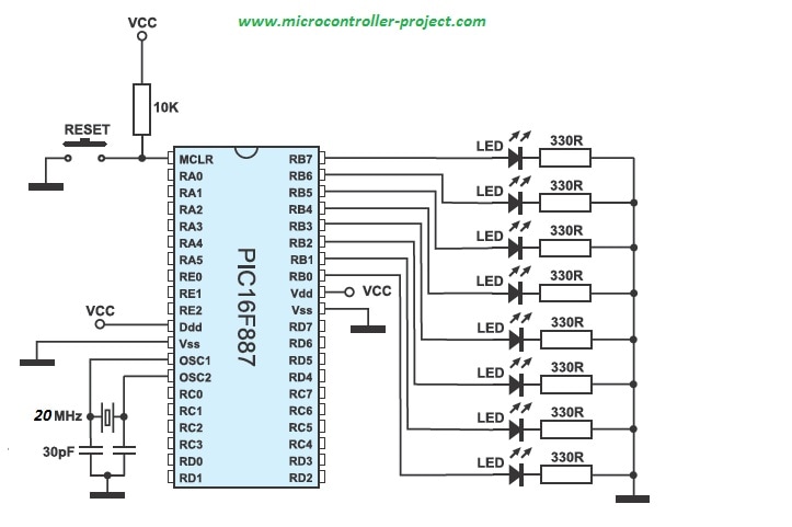
Project circuit diagram

Pic16f887 microcontroller is used in the project. I am going to toggle the led’s connected to Port-B of pic16f887 microcontroller. Port-B is an 8-bit port. 8 led’s are connected with port-b. Whole port is going to be toggled after 10 ms delay. An external 20 Mhz crystal is used as input clock source to pic16f887 microcontroller.  Timer-1 of pic16f887 is used for generating specific delay. Timer-1 is used in 16-bit mode. 

Note: ​Led’s anode is connected to pic microcontroller port-b pins and cathode is grounded with 330 ohm resistor placed in series. This configuration of led’s is a bad choice. I recommend you to connect the anode of led’s with external power source and connect the cathode with port-b pins of pic microcontroller. Resistor must be placed in series with the led to limit the current consumption by led.

My circuit configuration also worked but the led lights are too dim and its hard to see the effect of blinking/toggling in bright day light. I switched of room lights to see the clear pic microcontroller blinking led effect.   

Pic microcontroller specific delay generation to toggle leds.

Pic microcontroller specific delay generation to toggle leds.

Project code is written in mplabx ide and xc8 compiler is used for compiling code. The function Timer0Delay in the code contains 10 ms delay generation logic.
I am initialing the timer settings bits each time the Timer0Delay function is called on in code. The timers settings bits can be globally initialized once and in Timer0Delay function we can only run timer for desired time delay. The timer-1 settings bits are below and are part of Timer0Delay function. 

 T1CON=0x01;             //Timer-1 16-bit mode Prescaler 1:4
 TMR1H=0x30;             //Count High Byte
 TMR1L=0xD4;             //Count Low Byte

Download the project code/files. Folder contains the mplabx ide project files. Please give us your feed back on the project. In case you have any queries please write them below in the comments section.
Project Code/Files


Filed Under: Microcontroller Projects, PIC Microcontroller


Next Article

← Previous Article
Next Article →

Questions related to this article?
👉Ask and discuss on EDAboard.com and Electro-Tech-Online.com forums.


Tell Us What You Think!! Cancel reply

You must be logged in to post a comment.

Submit a Guest Post

submit a guest post

EE TECH TOOLBOX

“ee
Tech Toolbox: Power Efficiency
Discover proven strategies for power conversion, wide bandgap devices, and motor control — balancing performance, cost, and sustainability across industrial, automotive, and IoT systems.

EE Learning Center

EE Learning Center
“engineers
EXPAND YOUR KNOWLEDGE AND STAY CONNECTED
Get the latest info on technologies, tools and strategies for EE professionals.

HAVE A QUESTION?

Have a technical question about an article or other engineering questions? Check out our engineering forums EDABoard.com and Electro-Tech-Online.com where you can get those questions asked and answered by your peers!


RSS EDABOARD.com Discussions.

  • Can anyone please help me with this single board computer?
  • Anyone successfully communicated to the BlueNRG-M0 module on the B-L4S5I-IOT01A board
  • How to Build an Audio Tone Control?
  • Current version of LTspice not working on Windows 11?
  • Addressable Latch in My Logic Project

RSS Electro-Tech-Online.com Discussions

  • Measuring controller current output with a meter
  • KiCad custom symbol definition correct approach
  • restarting this Christmas project
  • Anyone In The US Ordered From AliExpress Recently?
  • My Advanced Realistic Humanoid Robots Project

Featured Tutorials

Real Time Hardware Filter Design

  • Practical implementation of bandpass and band reject filters
    Practical implementation of bandpass and band reject filters
  • Practical application of hardware filters with real-life examples
    Practical application of hardware filters with real-life examples
  • A filter design example
    A filter design example
  • Types of filter responses
    Types of filter responses
  • What are the two types of hardware filters?
    What are the two types of hardware filters?
  • What are hardware filters and their types?
    What are hardware filters and their types?
More Tutorials >

Recent Articles

  • Posifa sensors improve low-flow accuracy in compact systems
  • Acopian releases low-profile power supplies rated to 900 W
  • Octavo Systems OSDZU-3 REF Development Platform
  • Same Sky adds enclosure design to its audio engineering capabilities
  • Waterproof SMA-to-MHF I LK assemblies introduced by Amphenol RF

EE ENGINEERING TRAINING DAYS

engineering
Engineers Garage
  • Analog IC TIps
  • Connector Tips
  • Battery Power Tips
  • EDABoard Forums
  • EE World Online
  • Electro-Tech-Online Forums
  • EV Engineering
  • Microcontroller Tips
  • Power Electronic Tips
  • Sensor Tips
  • Test and Measurement Tips
  • 5G Technology World
  • Subscribe to our newsletter
  • About Us
  • Contact Us
  • Advertise

Copyright © 2025 WTWH Media LLC. All Rights Reserved. The material on this site may not be reproduced, distributed, transmitted, cached or otherwise used, except with the prior written permission of WTWH Media
Privacy Policy

Search Engineers Garage

  • Electronic Projects & Tutorials
    • Electronic Projects
      • Arduino Projects
      • AVR
      • Raspberry pi
      • ESP8266
      • BeagleBone
      • 8051 Microcontroller
      • ARM
      • PIC Microcontroller
      • STM32
    • Tutorials
      • Sensor Series
      • 3D Printing
      • AI
      • ARDUINO Compatible Coding
      • Audio Electronics
      • Battery Management
      • Beginners Electronics Series
      • Brainwave
      • Digital electronics (DE)
      • Electric Vehicles
      • EMI/EMC/RFI
      • EVs
      • Hardware Filters
      • IoT tutorials
      • LoRa/LoRaWAN
      • Power Tutorials
      • Protocol
      • Python
      • RPI Python Programming
      • Sensors
      • USB
      • Thermal management
      • Verilog
      • VHDL
    • Circuit Design
    • Project Videos
    • Components
  • Articles
    • Tech Articles
    • Insight
    • Invention Stories
    • How to
    • What Is
  • News
    • Electronic Product News
    • Business News
    • Company/Start-up News
    • DIY Reviews
    • Guest Post
  • Forums
    • EDABoard.com
    • Electro-Tech-Online
    • EG Forum Archive
  • DigiKey Store
    • Cables, Wires
    • Connectors, Interconnect
    • Discrete
    • Electromechanical
    • Embedded Computers
    • Enclosures, Hardware, Office
    • Integrated Circuits (ICs)
    • Isolators
    • LED/Optoelectronics
    • Passive
    • Power, Circuit Protection
    • Programmers
    • RF, Wireless
    • Semiconductors
    • Sensors, Transducers
    • Test Products
    • Tools
  • Learn
    • eBooks/Tech Tips
    • Design Guides
    • Learning Center
    • Tech Toolboxes
    • Webinars & Digital Events
  • Resources
    • Digital Issues
    • EE Training Days
    • LEAP Awards
    • Podcasts
    • Webinars / Digital Events
    • White Papers
    • Engineering Diversity & Inclusion
  • Guest Post Guidelines
  • Advertise
  • Subscribe