Described here is a CD 4027 hearted, battery employed circuit that serves as a solution for light and fan during the times of extreme humidity or power cuts. This emergency light circuit consists of a LED light and small DC fan which can sufficiently work for one person. The main advantage of this circuit is one can use any one or both devices at a particular time. The circuit does not consume much power so one can expect it work for a good amount of time.
[[wysiwyg_imageupload:7751:]]
Fig. 1: Prototype Of Emergency Light Circuit On Breadboard
This emergency light circuit is based on CD4027 IC which is the most commonly used JK flip flop IC. CD4027 is the master slave JK flip flop IC which works in toggle mode. Here, this IC can be used to change the state by signal applied to one or more control inputs and will have one or two outputs. In this circuit, output is only depended upon the current input.
CD4027 has four inputs namely J, K, Set and Reset and it contain two output namely Q and Q bar(Q not). The figure below shows the pin configuration of IC:

Fig. 2: Pin Configuration of CD4027 IC
Stage of flip flop is control by the logic level present at J and K input with some internal control. Changes in state occur at positive going transition of clock pulse. In this, set and reset pin are independent of clock and they are initiated when a high signal is present on any of the input pin.
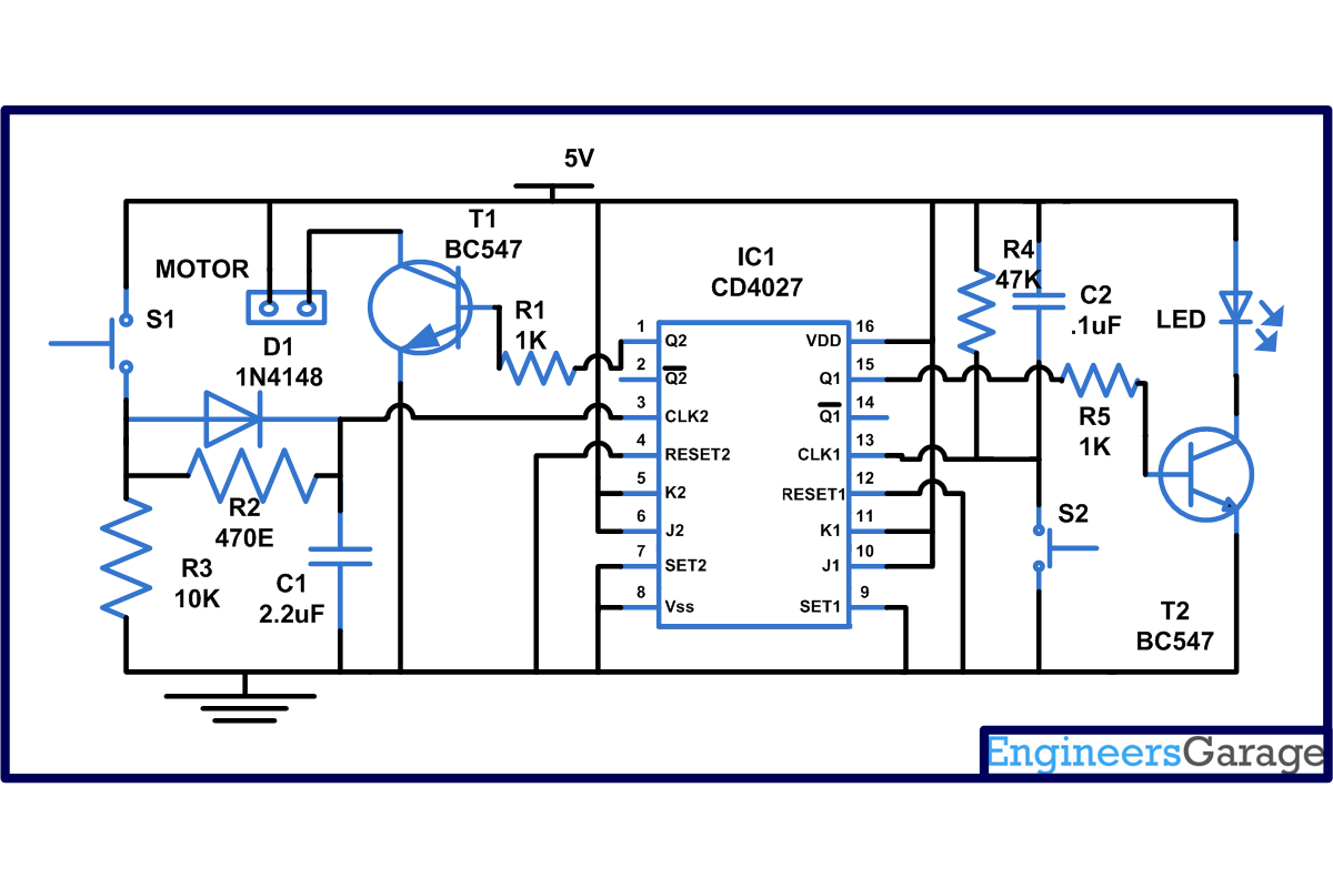
The circuit shown is triggered on the leading edge of the switch pulse which means that output changes when switch is once pressed. From the circuit you can see that both J and K are tied to high input meaning that at every negative or positive transition the clock pulse (pin 3) toggles between high to low. This can be verified with the help of truth table described below:
|
J |
K |
Q |
State |
|
0 |
0 |
Same State |
No change |
|
0 |
1 |
0 |
Reset |
|
1 |
0 |
1 |
Set |
|
1 |
1 |
Q bar |
Change the previous state |
But when you press the switch S1, a short pulse will pass into the clock input pin 3 of IC1 which in turns make the output pin 1 high. The output remains high till the clock input gets a second pulse. This activates the transistor which in turns on the load or motor connected to it. One can also connect a relay then with the help of it ,connect an AC output . When this second pulse comes on pin 3, the output of IC turns low and load becomes off. If you are not using the reset pin then ground that pin.
Similarly, if you want to turn on the light, press S2 switch: a short clock pulse is passed to pin 13 and the output pin 15 become high. The transistor connected to it will conduct and LED starts glowing until you again press the switch S2. If you want to increase the number of LED’s then use transistor which has more amplification capability.
Circuit Diagrams
Project Components
Project Video
Filed Under: Electronic Projects
Filed Under: Electronic Projects


Questions related to this article?
👉Ask and discuss on Electro-Tech-Online.com and EDAboard.com forums.
Tell Us What You Think!!
You must be logged in to post a comment.