While charging gadgets, we often come across those scenarios where the user plugs in the device but forgets to switch the electricity ON. Worse scenario is that where the user doesn’t plug up the gadget properly and leaves it, hoping it to get charged in quick succession of time.
Solving these few and more problems is this charger circuit which also has a battery flow indicator.
If the battery charger is not properly connected to the battery terminals, charging will not takes place. If the terminals, connecting clips etc are dirty or corroded, current will not pass into the battery. So even after prolonged charging, the battery will not attains full charge. The only way to confirm the flow of current is to connect an ampere meter in series with the positive so that when current passes, the needle deflects based on the amount of current passing. Here an LED indication is used to confirm the current flow into the battery.
The circuit includes following components:
1. Transformer
2. 1N4007 Diodes
3. Capacitor
4. Voltage Regulator 7815
5. LEDs
6. Transistor BD139
7. Resistors, and
8. 12V Battery

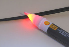
Fig. 1: Image Of Current Flow Indicator
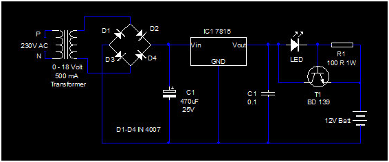
The battery charger circuit use a 0 – 18 volt 500 mA step-down transformer as low voltage AC source and diodes D1 through D4 as a full wave rectifier. The rectified DC is made ripple free by the smoothing capacitor C1. A positive voltage regulator IC 7815 is used to provide 15 volt regulated DC for charging. Regulated 15 volt DC passes through the LED and R1 at power on and LED glows in full brightness. LED used in the circuit is the new version low current 1 volt LED. When T1 gets sufficient base bias, it conducts and bypasses the voltage to the battery and the LED’s brightness reduces. LED turns on only when the clips are properly connected to the terminals, and its brightness reduces when the battery takes current. During the charging process, battery gets more than 13 volts which is sufficient for charging the Lead Acid battery.
Circuit Diagrams
Filed Under: Electronic Projects


Questions related to this article?
👉Ask and discuss on EDAboard.com and Electro-Tech-Online.com forums.
Tell Us What You Think!!
You must be logged in to post a comment.