[[wysiwyg_imageupload:1503:]]Mr. Subasis Pani is working as a Technician (Electrical) at UMSL, a sister concern company of IMFA Group, Therubali, Rayagada, Orisha, Inida.
1. Necessity of Starter
A Squirrel cage induction motor just before starting is similar to a poly phase transformer with a short-circuited secondary. If normal voltage is applied to the stationary motor then, as in the case of a transformer, a initial current, to the turn of 5 to 6 times the normal current or the normal rated current, will be drawn by the motor from the mains. This initial excessive current is objectionable, because it will produce line voltage (The potential difference or the voltage across two phases) drop, which in turn will affect the operation of the other electrical equipments and the lights connected to the same line.
The initial rush of current is controlled by applying a reduced voltage to the stator (motor) winding during the starting period and then the full normal voltage is applied when the motor has run up to speed. For the small capacity motors say up to 3H.P, full normal voltage can be applied at the start. How ever to start and stop the motor and to protect the winding from the over load current and low voltages, a starter is required in the motor circuit. In addition to this the starter may also reduce the applied voltage to the motor at the time of starting.
Starter
-
The starter is a safety and a protecting device by which we can control or minimize the starting current in order to prevent the motor windings of the respective motor.
Types of Starter as invented
Following are the different types of starter used for starting of the Squirrel cage induction motor.
1. Direct on line Starter(DOL Starter)
2. Star-Delta Starter(Hand operated)
3. Auto Star-Delta Starter
4. Step down transformer starter
5. Auto-transformer starter
In the above starters, except for the Direct on-line starter, reduce voltage is applied to the stator (motor) winding of the squirrel cage induction motor at the time of starting and regular voltage is applied once the motor pick up the speed.
The entire above invented starter can not be used as multipurpose operation.
- Selection of Starter
Many factors must be considered when selecting starting equipment. These factors include starting current, the full load current, voltage rating of motor, voltage (line voltage) drop, cycle of operation, types of load, motor protection and also safety of the operator.
Construction of Combination Starter
2. Combination Starter
It is a new type of starter which can works as DOL Starter (Direct on-line Starter) and as well as manual star-delta starter. The starter can only be operated by manually. This starter is made only by using three contactors and the safety and protecting devices.
- Construction of Combination Starter
The construction of combination starter is very simple. The combination starter consisting of following parts.
O.L.R. (Over Load Relay)
Contactors
Backup Fuses
MPCB
1. O.L.R (Over Load Relay)
It is a safety and a protecting device which trips the motor circuit when abnormal current (Either high current) flows through it. It consists of with a bimetallic plate or relay. Bimetallic relay can be adjusted to trip with in the range of 85 to 115 percent of the normal trip rating of the heater unit.
The tripping of the control circuit in the bimetallic relay result from the difference of expansion of two dissimilar metals fused together. Movement occurs if one of the metals expands more than the other when subjected to heat.
A bimetallic overload relay which is shown, under normal condition, the bimetallic strip pushes the pin against the leaf-spring tension, and the point contacts 95 and 96 are in a closed position and hence the no-volt coil circuit is completed while the motor is running. When a higher current passes through the heater coil connected to terminal 2 and 2’, the heat generated in the coil heats up the bimetallic strip which bends inward. Hence the pin retracts in the right hand direction and the leaf-spring open the contact between 95 and 96 to open the contactor. The relay cannot be reset immediately as the heat in the bimetallic strips some time to cooling.
Contactors
The contactor forms the main part in the construction of the Combination Starter. A contactor can be defined as a switching device capable of making, carrying and breaking a load circuit a frequency of 50 cycles per hour or more. It may be operated by manually (By Hand), electromagnetic, pneumatic or electro-pneumatic relays.
The contactor shown consisting of main contacts, auxiliary contacts and no-volt coil. As per figure there are three sets of No(Normally open)main contacts between terminals 1 and 2, 3 and 4, 5 and 6, two sets of normally open auxiliary contacts between terminals 23 and 24, 13 and 14, two sets of Nc(Normally close) contacts. Auxiliary contacts carry less current then main contacts. Normally contactors will not have the push-button station and Over Load relay as an integrated part, but will have to use as separate accessories along with the contactors to form the starter function.
- Back-up Fuse
Motors starters must never be used without back up fuses. The sensitive thermal relay mechanism is designed and calibrated to provide effective protection against overloads only. When sudden short circuit take place in a motor circuit, the over load relays, due to their inherent operating mechanism, takes a longer time to operate and open the circuit. Such delays will sufficient to damage the starter motor and connected circuit due to heavy in-rush of short-circuit current. This can be avoided by quick action, high-rupturing capacity fuses which, when used in the motor circuit, operate a faster rate and open the circuit. Hence H.R.C. fuses (High Rupturing Capacity Fuse) are recommended for protecting the installation as well as the thermal overload relay of the motor starter against short-circuits. In case of short-circuit, the back up fuses melts and open the circuit quickly.
- MPCB(Motor Protection Circuit Breaker)
It is one type circuit breaker which protects the motor by tripping the motor circuit when abnormal current flows through the motor because of over load, sort circuit, earth fault, etc.
How Combination Starter works
Functional Operation
Combine starter can be used as a Star-Delta starter and as well as DOL Starter.
- Combine Starter as a Star Delta Starter
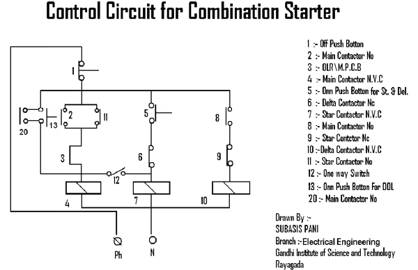
Combine starter can be used as Star-Delta starter. When the green push button pressed then the current flows through the point 6 (Delta Contactor Nc) to the Star contactor N.V.C. 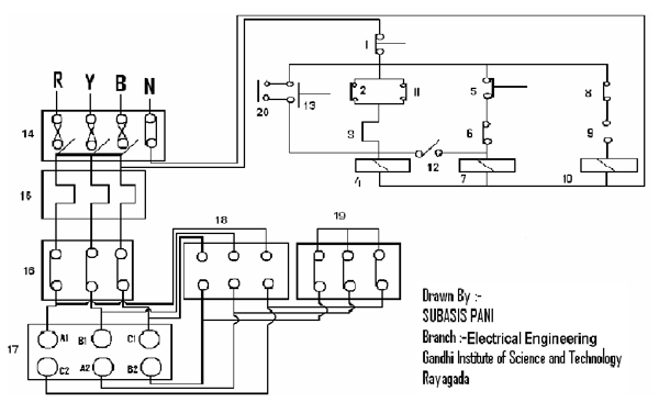 When the supply connected to the Star contactor N.V.C, The N.V.C get magnetized so that the point 9 (Star contactor Nc) becomes open so that the current could not pass through the Delta contactor N.V.C and on the other hand point 11(Star contactor No) close so that the current passed through the point 11 to the Main contactor N.V.C. Then the Main contactor N.V.C gets magnetized so that the point 2,8 (Main Contactor No) closed so that the current passed through the point 2 and 11. So in this condition the Main Contactor and the Star-contactor closed so that the windings of the respective motor connected in Star. So that the motor takes less amount of current.
 When the supply connected to the Star contactor N.V.C, The N.V.C get magnetized so that the point 9 (Star contactor Nc) becomes open so that the current could not pass through the Delta contactor N.V.C and on the other hand point 11(Star contactor No) close so that the current passed through the point 11 to the Main contactor N.V.C. Then the Main contactor N.V.C gets magnetized so that the point 2,8 (Main Contactor No) closed so that the current passed through the point 2 and 11. So in this condition the Main Contactor and the Star-contactor closed so that the windings of the respective motor connected in Star. So that the motor takes less amount of current.
Then remove the hand from the green push button so that the current could not passed through the Star contactor N.V.C, so that the Star contactor N.V.C demagnetized and the point 9 (Star contactor Nc) now closed and the point 11 (Star contactor No) now opened.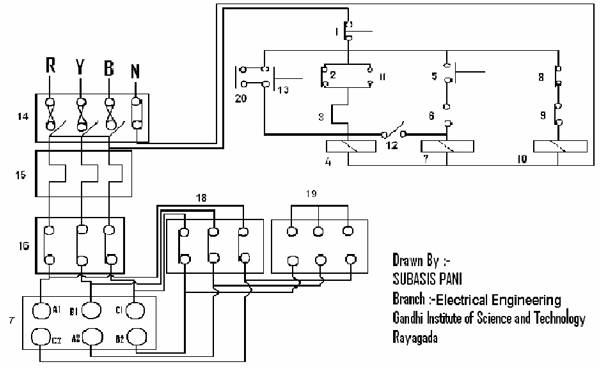 As a result the current passed through the points 8 (Main contactor No) which is now closed, 9 (Star contactor Nc) to the Delta Contactor N.V.C. So that the Now the Delta contactor N.V.C magnetized. Then the points 6 (Delta contactor Nc) now opened and the current can not be passed through the points 6 (Delta contactor Nc). So in this condition the Main Contactor and the Delta contactor closed so that the windings of the respective motor connected delta. So in this condition the motor takes normal current.
 As a result the current passed through the points 8 (Main contactor No) which is now closed, 9 (Star contactor Nc) to the Delta Contactor N.V.C. So that the Now the Delta contactor N.V.C magnetized. Then the points 6 (Delta contactor Nc) now opened and the current can not be passed through the points 6 (Delta contactor Nc). So in this condition the Main Contactor and the Delta contactor closed so that the windings of the respective motor connected delta. So in this condition the motor takes normal current.
- Combination Starter as a DOL Starter (Direct on-line Starter)
The Combination Starter can also be used as a DOL Starter. When the second on push button (Bell push switch) is pressed the current passed to the Main contactor N.V.C. 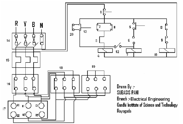 Then the Main contactor will magnetized and the point 2, 8 closed. So that the current can passed through the Main Contactor N.V.C and the Delta contactor N.V.C. In this condition the Main Contactor and the Delta contactor closed so that the windings of the respective motor connected delta, if it is necessary to run the motor in Star in Star then just press the Switch no 12.
 Then the Main contactor will magnetized and the point 2, 8 closed. So that the current can passed through the Main Contactor N.V.C and the Delta contactor N.V.C. In this condition the Main Contactor and the Delta contactor closed so that the windings of the respective motor connected delta, if it is necessary to run the motor in Star in Star then just press the Switch no 12.
Advantages
· Main advantage is that singly by the help of Combination Starter the motor can operated in Star and Delta as well as in Dol.
· It’s protecting capacity and efficiency is higher than other starter.
· Its cost is low as compared to other starters.
· Its fault rectification is very easy.
· It can be used as Main Switch in case of Domestic purpose.
Safety Precaution
· Before doing any Operation all the switches must be switched off.
· For running the motor select either we have to start the motor in Star-Delta or in DOL.
· When the motor operated in Star-Delta, do not press the DOL Push button and Vice versa.
SYMBOLS
1. Off Push Button For DOL and Star-Delta
2. Main Contactor No
3. Over Load Relay
4. Main Contactor N.V.C
5. On Pus Button For Star-Delta
6. Delta Contactor Nc
7. Star Contactor N.V.C
8. Main Contactor No
9. Star Contactor NC
10. Delta Contactor N.V.C
11. Star Contactor No
12. Switch for DOL / Star
13. On Push Button for DOL
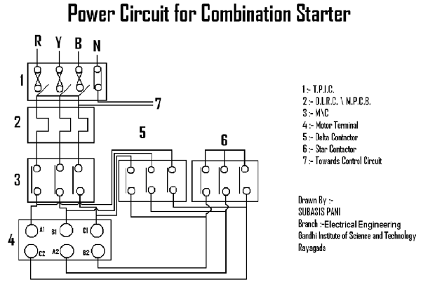
14. T.P.I.C (Triple Pole Iron Clad Main Switch)
15. Over Load Relay
16. Main Contactor
17. Motor Terminal
18. Delta Contactor
19. Star Contactor
20. Main Contactor No
Project Source Code
Circuit Diagrams
Filed Under: Electronic Projects


Questions related to this article?
👉Ask and discuss on EDAboard.com and Electro-Tech-Online.com forums.
Tell Us What You Think!!
You must be logged in to post a comment.