Engineers Garage

  • Electronic Projects & Tutorials
    • Electronic Projects
      • Arduino Projects
      • AVR
      • Raspberry pi
      • ESP8266
      • BeagleBone
      • 8051 Microcontroller
      • ARM
      • PIC Microcontroller
      • STM32
    • Tutorials
      • Audio Electronics
      • Battery Management
      • Brainwave
      • Electric Vehicles
      • EMI/EMC/RFI
      • Hardware Filters
      • IoT tutorials
      • Power Tutorials
      • Python
      • Sensors
      • USB
      • VHDL
    • Circuit Design
    • Project Videos
    • Components
  • Articles
    • Tech Articles
    • Insight
    • Invention Stories
    • How to
    • What Is
  • News
    • Electronic Product News
    • Business News
    • Company/Start-up News
    • DIY Reviews
    • Guest Post
  • Forums
    • EDABoard.com
    • Electro-Tech-Online
    • EG Forum Archive
  • DigiKey Store
    • Cables, Wires
    • Connectors, Interconnect
    • Discrete
    • Electromechanical
    • Embedded Computers
    • Enclosures, Hardware, Office
    • Integrated Circuits (ICs)
    • Isolators
    • LED/Optoelectronics
    • Passive
    • Power, Circuit Protection
    • Programmers
    • RF, Wireless
    • Semiconductors
    • Sensors, Transducers
    • Test Products
    • Tools
  • Learn
    • eBooks/Tech Tips
    • Design Guides
    • Learning Center
    • Tech Toolboxes
    • Webinars & Digital Events
  • Resources
    • Digital Issues
    • EE Training Days
    • LEAP Awards
    • Podcasts
    • Webinars / Digital Events
    • White Papers
    • Engineering Diversity & Inclusion
    • DesignFast
  • Guest Post Guidelines
  • Advertise
  • Subscribe

Configure built-in ADC of LPC2148

By Dishant Shah April 21, 2008

While dealing with controllers we are dealing with digital signals but real world is analog. In real world all natural quantities like temperature, pressure, light intensity etc. are analog. If we have to deal with such quantities using embedded systems, we have to convert these analog quantities which can be understood and proceed by digital signal. Devices used for this purpose is known as ADC. Special ICs such as ADC0804, ADC0808, ADC0809, Serial ADC MAX1112 etc. are handy for this. Nowadays, many controllers are having inbuilt ADC. LPC2148 of ARM7 family is one of the widely used controller and it also has multichannel ADC inbuilt. In this article, we will understand how to use inbuilt ADC of LPC2148.
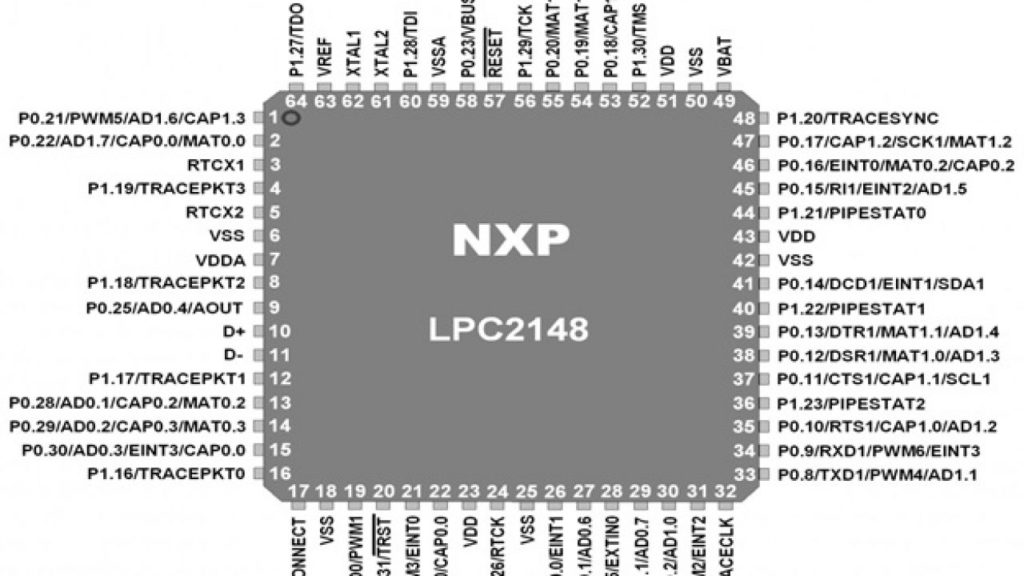

ADCs act as a bridge between the analog real world and the digital world of controllers. ADC converts analog voltage into a digital number, which can be understood and proceed by the controller. Let us understand this with an example.

LPC 2148 operates on a 3.3V supply. Suppose we use 10 bit ADC, 3.3V correspondences to 2^10=1023.  Half of 3.3V= 1.65V can be represented by 512, 0V as digital value 0, and so on.

Before proceeding further, let us first understand a few basic concepts related to ADC.

1.   Resolution:

Analog voltage will be converted into a digital number. The number of bits required to store the digital number, let say n bits, is known as resolution. If a digital number is represented with n bits, the maximum value is 2n. So for 10 bit ADC resolution is 10 bit, and the maximum value is 210=1023.

2.   Step size

Minimum voltage, which can be distinguished by the controller, is known as the step size.

Step size= Maximum Voltage/ 2n where n= resolution

For LPC 2148, Maximum voltage=3.3V and n=10

So step size=3.3/1023= 0.0032258064 V = 3.23 mv (Approx.)

The voltage between 0 and 3.23 mV will be identified as the same for the controller. This identifies the accuracy of ADC.

3.   Conversion time

Converting analog voltage into digital will not be done immediately. It will take a few mili-seconds. The higher the resolution, the higher is the conversion time.

So now, let us start with the ADC of LPC 2148. First, let us have a quick look at the features of it.

> LPC 2148 has two inbuilt ADC modules known as ADC0 and ADC1.

> Maximum resolution of ADC is 10 bit. It is configurable by programming.

> ADC0 has 6 channels

> ADC1 has 8 channels

> Both ADC supports a maximum clock frequency of 4.5 MHz (Operating frequency decides the conversion time)

Pins required for ADC are as follows.
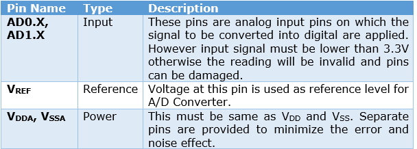
Pins for ADC of LPC2148

There are various registers associated with ADC0 and ADC1. Commonly user registers are ADC Control Registers (AD0CR & AD1CR) and ADCGR- ADC Global data register.
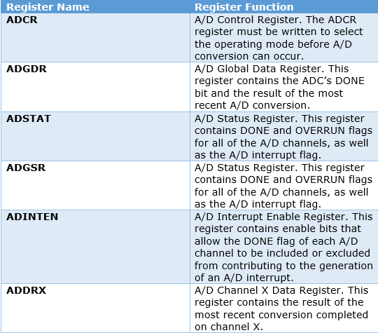
Registers for ADC of LPC2148

Let us understand all registers one by one.

The most important register for ADC is ADCR. Let us see the functions of each bit of this register.


ADCR

ADCR

Another important register is AD0GR and AD1GR. Bits of this register are as follows.

ADGR

The result of the conversion is stored in the A/D Data register, which has the following structure.

Result of ADC Conversion stored

Steps for programming:

1.   Configure input pin as an analog input pin for ADC

2.   Select channel of ADC

3.   Start conversion

4.   Wait till conversion is done

5.   Read data of ADC Conversion output

6.   Convert number into separate digits like 512 as separate 5,1 and 2

7.   Display digits on LCD

8.   Repeat the above steps

Project Source Code

###

//Program to Interface ADC with LPC2148

#include                   /* LPC21xx definitions */             
#include "lcd4bit.h"
 
void init_adc(){
  PINSEL1 |= 0X01000000;
  ADCR = 0X00200602;
  }
 
void delay(int n)    /* generates one milisecond delay  */
  {
   int i,j;
   for (i=1; i<=n; i++)
   for(j=0; j<=10000; j++);
   }
 
int read_adc(void){
  int val;
   ADCR |= 0x01000000;                 /* Start A/D Conversion           */
  do {
    val = ADDR;                        /* Read A/D Data Register         */
    } while (!(val & 0x80000000));     /* Wait for end of A/D Conversion */
  ADCR &= ~0x01000000;                 /* Stop A/D Conversion            */
  val >>=6;
   val= val & 0x3FF;
   return(val);
  }
 
 
int main(void)
{
int dat,i=0;
char buf[5];
init_adc();
init_lcd();
 
lcd_command(0x01);
lcd_command(0x80);
printlcd("ADC Interfacing");
lcd_command(0xC0);
printlcd("with LPC2148");
delay(2000);
 
lcd_command(0x01);
lcd_command(0x80);
printlcd("Developed By:");
lcd_command(0xC0);
printlcd("Dishant Shah");
delay(2000);
 
lcd_command(0x01);
lcd_command(0x80);
printlcd("  EMERTECH ELE. ");
lcd_command(0xC0);
printlcd("SYSTEMS,Vadodara");
delay(3000);
 
lcd_command(0x01);
lcd_command(0x80);
printlcd("Digital Value");
lcd_command(0xC0);
while(1)
{Delay(1000000);
 
lcd_command(0xC0);
dat = read_adc();
i=0;
 
while(dat>0)
 {
 buf[i]=dat%10;
 dat=dat/10;
 i++;
 }
 
while(--i >= 0){lcd_data(buf[i]+'0');
}
delay(10);
}}


###


Project Source Code

###

//Program to Interface LCD with LPC2148
#include
#include "lcd4bit.h"
 
 
void Delay(unsigned long b){ 
  while (--b!=0);
  }
 
 void write_command(int cmd) {
  IO1CLR  |= 0x00f00000;                 /* Clear D4-D7  */
  IO1CLR  |= 0x00040000;                /* Read/Write = 0 */
  IO1CLR  |= 0X00020000;                    /* Register Select = 0,Command */
  IO1SET  |= 0x00f00000 & cmd;      /* Set D4-D7    */
  IO1SET  |= 0X00080000;                /* Enable = 1 */  
  Delay(30000);
  IO1CLR  |= 0x00080000;                 /* set E to low   */
  }
 
void write_data(int dat) {
  IO1CLR  |= 0x00f00000;                 /* Clear D4-D7  */
  IO1CLR  |= 0x00040000; /* Read/Write = 0 */
  IO1SET  |= 0X00020000;     /* Register Select = 1,Data */
  IO1SET  |= 0x00f00000 & dat;   /* Set D4-D7    */
  IO1SET  |= 0X00080000; /* Enable = 1 */
  Delay(30000);           //delay ~2ms
  IO1CLR  |= 0x00080000; /* Set E to low   */
  }
 
void lcd_data(char dat){
  write_data(dat << 16);
  write_data(dat << 20);
  }
 
void lcd_command(char cmd){
  write_command(cmd << 16);
  write_command(cmd << 20);
  }
  
void printlcd(char *CPtr){
  while(*CPtr != '') {
lcd_data(*CPtr);
    CPtr++;
Delay(20000);
}
  }


void init_lcd(void) {
  IO1DIR |= 0x00FE0000;    
  Delay(200000) ;
  write_command(0x30 << 16); 
  Delay(100000);
  write_command(0x30 << 16);
  Delay(100000);
  write_command(0x30 << 16);
  Delay(100000);
  write_command(0x20 << 16);
 
  lcd_command(0x01);                         /* clear display */
  lcd_command(0x06);                         /* auto address inc */
  lcd_command(0x0c);                         /* cursor off */
  lcd_command(0x80);                         /* first location */
  }


###


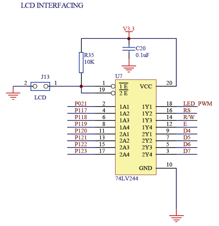
Circuit Diagrams

schematic1
4.-Circuit-Diagram_1

Project Video

https://www.youtube.com/watch?v=QW_sTXWsVao&feature=youtu.be


Filed Under: ARM


Next Article

← Previous Article
Next Article →

Questions related to this article?
👉Ask and discuss on EDAboard.com and Electro-Tech-Online.com forums.


Tell Us What You Think!! Cancel reply

You must be logged in to post a comment.

EE TECH TOOLBOX

“ee
Tech Toolbox: 5G Technology
This Tech Toolbox covers the basics of 5G technology plus a story about how engineers designed and built a prototype DSL router mostly from old cellphone parts. Download this first 5G/wired/wireless communications Tech Toolbox to learn more!

EE Learning Center

EE Learning Center
“engineers
EXPAND YOUR KNOWLEDGE AND STAY CONNECTED
Get the latest info on technologies, tools and strategies for EE professionals.

HAVE A QUESTION?

Have a technical question about an article or other engineering questions? Check out our engineering forums EDABoard.com and Electro-Tech-Online.com where you can get those questions asked and answered by your peers!


RSS EDABOARD.com Discussions

  • How to start a startup in VLSI
  • UART Basic Before Writing Code
  • Single ended measuring ports and balanced antenna
  • Thermal modelling of repetitive power pulse
  • PFAS-Free Die Attach Paste

RSS Electro-Tech-Online.com Discussions

  • Fun with AI and swordfish basic
  • Simple LED Analog Clock Idea
  • Microinverters and storeage batteries?
  • PIC KIT 3 not able to program dsPIC
  • Is AI making embedded software developers more productive?

Featured – LoRa/LoRaWan Series

  • What is the LoRaWAN network and how does it work?
  • Understanding LoRa architecture: nodes, gateways, and servers
  • Revolutionizing RF: LoRa applications and advantages
  • How to build a LoRa gateway using Raspberry Pi
  • How LoRa enables long-range communication
  • How communication works between two LoRa end-node devices

Recent Articles

  • How to design a weather station using ESP8266
  • RPi Python Programming 21: The SIM900A AT commands
  • RPi Python Programming 22: Calls & SMS using a SIM900A GSM-GPRS modem
  • RPi Python Programming 23: Interfacing a NEO-6MV2 GPS module with Raspberry Pi
  • RPi Python Programming 24: I2C explained

EE ENGINEERING TRAINING DAYS

engineering

Submit a Guest Post

submit a guest post
Engineers Garage
  • Analog IC TIps
  • Connector Tips
  • Battery Power Tips
  • DesignFast
  • EDABoard Forums
  • EE World Online
  • Electro-Tech-Online Forums
  • EV Engineering
  • Microcontroller Tips
  • Power Electronic Tips
  • Sensor Tips
  • Test and Measurement Tips
  • 5G Technology World
  • Subscribe to our newsletter
  • About Us
  • Contact Us
  • Advertise

Copyright © 2025 WTWH Media LLC. All Rights Reserved. The material on this site may not be reproduced, distributed, transmitted, cached or otherwise used, except with the prior written permission of WTWH Media
Privacy Policy

Search Engineers Garage

  • Electronic Projects & Tutorials
    • Electronic Projects
      • Arduino Projects
      • AVR
      • Raspberry pi
      • ESP8266
      • BeagleBone
      • 8051 Microcontroller
      • ARM
      • PIC Microcontroller
      • STM32
    • Tutorials
      • Audio Electronics
      • Battery Management
      • Brainwave
      • Electric Vehicles
      • EMI/EMC/RFI
      • Hardware Filters
      • IoT tutorials
      • Power Tutorials
      • Python
      • Sensors
      • USB
      • VHDL
    • Circuit Design
    • Project Videos
    • Components
  • Articles
    • Tech Articles
    • Insight
    • Invention Stories
    • How to
    • What Is
  • News
    • Electronic Product News
    • Business News
    • Company/Start-up News
    • DIY Reviews
    • Guest Post
  • Forums
    • EDABoard.com
    • Electro-Tech-Online
    • EG Forum Archive
  • DigiKey Store
    • Cables, Wires
    • Connectors, Interconnect
    • Discrete
    • Electromechanical
    • Embedded Computers
    • Enclosures, Hardware, Office
    • Integrated Circuits (ICs)
    • Isolators
    • LED/Optoelectronics
    • Passive
    • Power, Circuit Protection
    • Programmers
    • RF, Wireless
    • Semiconductors
    • Sensors, Transducers
    • Test Products
    • Tools
  • Learn
    • eBooks/Tech Tips
    • Design Guides
    • Learning Center
    • Tech Toolboxes
    • Webinars & Digital Events
  • Resources
    • Digital Issues
    • EE Training Days
    • LEAP Awards
    • Podcasts
    • Webinars / Digital Events
    • White Papers
    • Engineering Diversity & Inclusion
    • DesignFast
  • Guest Post Guidelines
  • Advertise
  • Subscribe