Modbus is a widely used communication protocol and an open-source industrial networking standard. Developed in 1979 by Modicon (now Schneider Electric), Modbus has become a standard in the automation and industrial control systems (ICS) industries.
The communication protocol is known for its simplicity and easy-to-follow troubleshooting feature. It uses a master-slave or client-server communication model, where a master or client device initiates requests to read or write data to slave or server devices.
The standard protocol is hardware-agnostic, meaning it can be implemented on various devices and platforms, including different types of microcontrollers (including Arduino) and operating systems. Modbus supports various data types, including discrete inputs, coils (digital outputs), input registers, and holding registers (analog data). It handles analog and digital data.
Modbus has reliably been used in industrial environments for decades for automation, energy management, building automation, SCADA systems, agricultural monitoring, pump and motor control systems, and more. Remote terminal units (RTUs) often use it to transmit data to a central control center. Modbus can also be easily adapted for specific application requirements while using other industrial protocols or communication standards.
An advantage of using Modbus on Arduino is its ability to handle complex data communication at long distances. For example, Arduino can communicate with software/apps, human-machine interfaces, peripheral devices, or microcontrollers. Modbus is well-suited for small to medium-sized automation applications and ideal for cost-conscious projects.
Modbus protocols have three types: Modbus ASCII, Modbus RTU, and Modbus TCP. In this article, we’ll turn Arduino into a Modbus device using Modbus ASCII/RTU and Modbus TCP. To do so, we’ll set-up communication between two Arduino boards on Modbus.
What is Modbus?
Modbus is a popular low-speed, open serial communication protocol commonly used in the automation industry and maintained by the Modbus organization. It serves as a link between PLCs and intelligent automation devices.
With the help of the serial protocol, which is based on a master-slave setup, a Modbus client can establish contact with as many as 247 Modbus servers. Standard RS-485 or RS-232 ports facilitate the physical interface. The bus includes a twisted pair of cables, insulated or not, with both ends terminated in 150 ohms. The cable can be quickly linked to the devices using RJ-45 connectors, screw terminals, or 9-pin D-shell connectors.
The Modbus client is generally a supervisory computer within a human-machine interface (HMI) or a supervisory control and data acquisition (SCADA) system. The remote terminal units (RTU) — like sensor modules, programmable logic controllers (PLC), or programmable automation controllers (PAC) — are the Modbus servers. To learn more about the Modbus protocol, check out this link.
Why Modbus?
Modbus is a versatile and reliable protocol. It’s currently the most commonly used device for industrial automation. It’s the communication standard for connecting and controlling devices such as PLCs, sensors, actuators, and HMIs. It can also collect data from energy meters, monitor power consumption, and control HVAC (heating, ventilation, and air conditioning) systems. It can also integrate various building subsystems, including lighting, HVAC, security, and access control.
Modus is ideal for remote monitoring and telemetry applications, including monitoring environmental conditions, water levels, or equipment status in remote locations. As the protocol can efficiently handle analog and digital data, it’s also ideal for data acquisition from sensors and instruments in laboratory, research, and test setups.
The protocol is frequently used as the communication protocol in SCADA systems to collect data from remote field devices.
Modbus is versatile and reliable for nearly any kind of automation application, whether small or medium. It allows half and full-duplex communication over long distances. Modbus RTU can extend up to 1200 meters (on RS-485), while Modbus TCP has no limit on range. Modbus also permits bidirectional communication between devices and connects with multiple devices in a network.
When to use Modbus with Arduino?
If Arduino must interface with a PLC, HMI, or a peripheral device, Modbus is the obvious choice. It allows Arduino to communicate with any microcontroller or device over an extended range.
Home or office automation applications can benefit from the protocol as the protocol lets master and slave communicate in both directions.
Typical communication protocols like UART, I2C, and SPI available on microcontrollers (including Arduino) have their own limitations. When a network gets too complex, and multiple devices need to communicate two-way, Modbus is the ideal communication protocol to handle such complexity without making the circuit or code cumbersome.
For sensor networks on Arduino, Modbus again guarantees reliable, long-range, centralized and well-managed communication.
How does Modbus work?
A Modbus network can have one or more master devices and multiple slave devices. The master device is called a Modbus client, and the slaves are Modbus servers.
On serial versions of Modbus, a master device can communicate with up to 247 devices. The Ethernet version lets a master talk to hundreds of devices on a single Ethernet network segment.
The communication is based on a request-response method. The master sends a request to one or more slave devices, specifying the type of operation (read or write) and the data address it wants to access. The data types that can be read or written include discrete inputs (binary data), coils (binary outputs), input registers (analog data), and holding registers (analog data).
Each data point in a Modbus network has a unique address. The master specifies the address of the data it wants to access in the request when it communicates with a slave. For example, a Modbus device might have discrete inputs starting at address 1, coils starting at address 10001, input registers starting at address 30001, and holding registers starting at address 40001.
For a Modbus request, the type of operation is specified by a function code. Common function codes include F01 (Read Discrete Inputs), F02 (Read Coils), F03 (Read Analog Input Registers), F04 (Read Analog Output Holding Registers), F05 (Write Single Coil), F06 (Write Single Holding Register), F15 (Write Multiple Coils), and F16 (Write Multiple Holding Registers). When a slave device receives a valid request, it processes the request and sends a response back to the master. The response contains the requested data or an acknowledgment of a successful write operation. The master typically polls slave devices at regular intervals to collect data or issue commands.
There are error-checking mechanisms like CRC or LRC to ensure data integrity during transmission. The response provides error codes to indicate issues such as invalid requests or communication problems. To learn more about the workings of Modbus, check out this link.
Modbus RTU/ASCII and Modbus TCP
There are three popular Modbus types: Modbus RTU, Modbus ASCII, and Modbus TCP. Though Modbus RTU and Modbus ASCII are different protocol versions, both are used in serial communication environments, such as RS-232, RS-422, and RS-485.
Modbus RTU is more commonly associated with RS-485 due to its binary nature. Many devices support both Modbus ASCII and Modbus RTU. Modbus ASCII and Modbus RTU can be implemented with the same hardware on Arduino. However, it’s important to distinguish between them.
- Modbus RTU represents data in binary format as 8-bit raw binary values, whereas for Modbus ASCII, data is transmitted as ASCII characters where two ASCII characters represent each byte.
- Modbus RTU frames consist of binary data with start and stop bits for synchronization, while Modbus ASCII frames start with a colon (“:”) character and end with a carriage return and line feed (“\r\n”) sequence.
- Modbus RTU uses cyclic redundancy check (CRC) for error detection in the data frame, while Modbus ASCII uses LRC (longitudinal redundancy check) for error detection. Modbus RTU is commonly used in industrial applications, especially in environments requiring high-speed communication.
- Modbus ASCII is preferred where human-readable communication or troubleshooting is essential. A microcontroller should use Modbus RTU when talking with sensor modules. But when communicating with HMI devices, Modbus ASCII is a better solution.
- Modbus TCP operates over Ethernet networks using the TCP/IP protocol suite. Modbus RTU/ASCII are better suited for point-to-point or multi-drop serial networks. Modbus TCP is designed for Ethernet-based local area networks (LANs) and can communicate over longer distances using standard networking equipment.
- Modbus TCP uses standard Ethernet frames, which differ from the data frames of Modbus RTU/ ASCII. It relies on TCP/IP for reliable data transport. Modbus RTU/ASCII require point-to-point or multi-drop network topologies. Modbus TCP is quite flexible and allows network topologies like star, bus, or ring configurations.
- Modbus RTU/ASCII supports single transactions only. When a master sends a request over Modbus RTU/ ASCII, it must wait for a Modbus response or timeout before sending another request. However, Modbus TCP supports multiple transactions, so a master can send several requests on Modbus TCP and doesn’t have to wait for a Modbus response or timeout. The response to a request is identified by a transaction ID, where the transaction ID remains the same for the request and response.
- Although Modbus RTU/ASCII are commonly used in industrial automation and control systems where serial communication is prevalent, Modbus TCP is more suitable for modern industrial networks and building automation.

Turning Arduino into a Modbus device
If Arduino must communicate with a PLC or HMI device, it’s necessary first to turn Arduino into a Modbus device. Arduino can easily be configured to participate in Modbus RTU/ASCII/TCP networks. To do so, hardware and software components are required.
To implement Modbus RTU/ASCII, Arduino must communicate over the RS-485, RS-422, or RS-232 ports. The RS-485 is the most popular port to use. This requires interfacing Arduino with an RS-485 to TTL converter. The Arduino Modbus library is also needed.
To implement Modbus TCP, Arduino must communicate over the TCP/IP stack. This requires an Ethernet shield over Arduino. The Arduino Modbus library is needed, which can be downloaded from this Github link.
RS485 to TTL converter
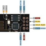
To convert Arduino into a Modbus RTU/ASCII network as master or a slave, an RS485 transceiver or RS485-to-TTL converter is required. One such transceiver based on the MAX485 chip is in the image below.

On a Modbus, a binary ‘0’ is represented by a voltage level of +2 to +6V. The binary ‘1’ is represented by a voltage level of -2 to -6V. Arduino operates on TTL logic levels, so a logic converter as shown above is required.
An RS485 transceiver has the following pin diagram.
![]()
The pin configuration of the RS-485 transceiver is described in the table below.

To use the module as a transmitter, connect the RE and DE pins to 5V and connect the DI pin to Arduino’s TX pin. Data is sent from Arduino’s TX pin to the module DI pin, which is then sent through AB.
To use the module as a receiver, connect the RE and DE pins to Ground and connect the RO pin to Arduino’s RX pin. Data received by AB is sent to the RO pin, which is connected to Arduino’s RX pin — so, the data is read by Arduino.
Arduino Modbus library
ArduinoModbus is a free, open-source library for Arduino boards to communicate with Modbus devices over serial (RS485) and network (TCP) connections. It’s based on the libmodbus library, but has been modified to use the Arduino Serial/RS485 and Client APIs. It’s an easy-to-use API for sending and receiving Modbus messages, handling Modbus framing and error checking. It also supports all Modbus function codes.
The library is compatible with the megaavr, samd, mbed_nano, mbed_portenta, and mbed_opta architectures and can be used on Arduino Uno, Arduino Nano, Arduino Mega, Arduino Due, Arduino MKR Zero, Arduino MKR 1000, Arduino MKR WiFi 1010, Arduino MKR WAN 1310, Arduino MKR FOX 1200, Arduino MKR GSM 1400, Arduino MKR NB 1500, Arduino Portenta H7, Arduino Nano 33 IoT, and Arduino Nano RP2040 Connect.
It can also be used on other Arduino-compatible boards, such as the Genuino M100 and the Adafruit Feather M0. The library can be installed through Arduino IDE’s library manager or downloaded from this Github link.
The library provides the following method to configure Arduino as Modbus RTU client.
modbusRTUClient.begin():
The function starts the Modbus RTU client with the specified parameters. The function returns ‘1’ on success and ‘0’ on failure. It has the below syntax.
ModbusRTUClient.begin(baudrate);
ModbusRTUClient.begin(baudrate, config);
The library provides the following methods to configure Arduino as a Modbus TCP client.
ModbusTCPClient(): The method creates a Modbus TCP client using the provided client for the transport. The method has the following syntax:
ModbusTCPClient(client);
modbusTCPClient.begin(): The method starts the Modbus TCP client with the specified parameters. It has this syntax:
modbusTCPClient.begin(ip, port);
modbusTCPClient.connected(): The method returns the connection status. It has this syntax:
modbusTCPClient.connected();
modbusTCPClient.stop(): The method disconnects the server. It has this syntax:
modbusTCPClient.stop();
The library provides the following method to configure Arduino as a Modbus RTU server.
modbusRTUServer.begin(): The method starts the Modbus RTU server with the specified parameters. The function returns ‘1’ for success or ‘0’ for failure. It has the following syntax:
ModbusRTUServer.begin(id, baudrate);
ModbusRTUServer.begin(id, baudrate, config);
The library provides the following methods to configure Arduino as a Modbus TCP server.
ModbusTCPServer(): The method creates a Modbus TCP server. It has the following syntax.
ModbusTCPServer();
modbusTCPServer.begin(): The method starts the Modbus server. It may require slave ID passed as an argument. If no ID is provided, it defaults to 0xFF (TCP). It has this syntax:
modbusTCPserver.begin();
modbusTCPserver.begin(id);
modbusTCPServer.accept(): The method accepts a client connection. It has this syntax:
modbusTCPserver.accept(client);
The library provides the following methods to operate as a Modbus client.
client.coilRead(): The method performs a “Read Coils” operation for the specified address for a single coil. It takes slave ID and/or address as arguments. It has this syntax:
int coilRead(int address);
int coilRead(int id, int address);
client.discreteInputRead(): The method performs a “Read Discrete Inputs” operation for the specified address for a single discrete input. It takes slave ID and/or address as arguments. It has this syntax:
int discreteInputRead(int address);
int discreteInputRead(int id, int address);
client.holdingRegisterRead(): The method performs a “Read Holding Registers” operation for a single holding register. It takes slave ID and/or address as arguments. It has this syntax:
long holdingRegisterRead(int address);
long holdingRegisterRead(int id, int address);
client.inputRegisterRead(): The method performs a “Read Input Registers” operation for a single input register. It takes slave ID and/or address as arguments. It has this syntax:
long inputRegisterRead(int address);
long inputRegisterRead(int id, int address);
client.coilWrite(): The method performs a “Write Single Coil” operation for the specified address and value. It takes id of the target slave, address of the operation and coil value to write as arguments. It has this syntax:
int coilWrite(int address, uint8_t value);
int coilWrite(int id, int address, uint8_t value);
client.holdingRegisterWrite(): The method performs a “Write Single Holding Register” operation for the specified address and value. It takes the ID of the target slave, the address of the operation, and the holding register value to write as arguments. It has this syntax:
int holdingRegisterWrite(int address, uint16_t value);
int holdingRegisterWrite(int id, int address, uint16_t value);
client.registerMaskWrite(): The method performs a “Mask Write Registers” operation for the specified address, AND mask and OR mask. It takes the ID of the target slave, the address of the operation, AND mask to use for operation, and OR mask to use for operation as arguments. It has this syntax:
int registerMaskWrite(int address, uint16_t andMask, uint16_t orMask);
int registerMaskWrite(int id, int address, uint16_t andMask, uint16_t orMask);
client.beginTransmission(): The method begins the process of a writing multiple coils or holding registers. It takes the ID of the target slave, type of write to perform (COILS or HOLDING_REGISTERS), the address of the operation, and the number of values to write as arguments. It has this syntax:
int beginTransmission(int type, int address, int nb);
int beginTransmission(int id, int type, int address, int nb);
client.write(): The method sets the values of a write operation started by beginTransmission(). It takes value to write as an argument. The method returns ‘1’ on success or ‘0’ on failure. It has this syntax:
int write(unsigned int value);
client.endTransmission(): The method ends the process of writing multiple coils or holding registers. It returns ‘1’ on success or ‘0’ on failure. It has this syntax:
int endTransmission();
client.requestFrom(): The method reads multiple coils, discrete inputs, holding registers, or input register values. It uses available() and read() to process the read values. It takes the ID of the target slave, the type of read to perform (COILS, DISCRETE_INPUTS, HOLDING_REGISTERS, or INPUT_REGISTERS), the start address to use for operation, and the number of values to read as arguments. It has this syntax:
int requestFrom(int type, int address, int nb);
int requestFrom(int id, int type, int address,int nb);
client.available(): The method queries the number of values available to read after calling requestFrom(). It has the following syntax.
int available();
client.read(): The method reads a value after calling requestFrom(). It returns -1 on failure and a value on success. It has this syntax:
long read();
client.lastError(): The method reads the last error reason as a string. It has this syntax:
const char* lastError();
client.end(): The method stops the client and perform clean up. It has this syntax:
void end();
The library provides following methods to operate as a Modbus server.
modbusServer.configureCoils(): The method configures the server’s coils. It takes the beginning address of the coils and the number of coils to configure as arguments. It has the following syntax:
int configureCoils(int startAddress, int nb);
modbusServer.configureDiscreteInputs(): The method configures the server’s discrete inputs. It returns ‘0’ on success or ‘1’ on failure. It takes the beginning of the address of discrete inputs and the number of discrete inputs to configure as arguments. It has this syntax:
int configureDiscreteInputs(int startAddress, int nb);
modbusServer.configureHoldingRegisters(): The method configures the server’s holding registers. It takes the beginning of the address of the holding registers and the number of holding registers to configure as arguments. It has this syntax:
int configureHoldingRegisters(int startAddress, int nb);
modbusServer.configureInputRegisters(): The method configures the server’s input registers. It takes the beginning of the address of the input registers and the number of input registers to configure as arguments. It has this syntax:
int configureInputRegisters(int startAddress, int nb);
modbusServer.coilRead(): The method performs a “Read Coils” operation for the specified address for a single coil. It takes the ID of the target slave and/or address to use for operation as arguments. It has this syntax:
int coilRead(int address);
int coilRead(int id, int address);
modbusServer.discreteInputRead(): The method performs a “Read Discrete Inputs” operation for the specified address for a single discrete input. It takes the ID of the target slave and/or address to use for operation as arguments. It has this syntax:
int discreteInputRead(int address);
int discreteInputRead(int id, int address);
modbusServer.holdingRegisterRead(): The method performs a “Read Holding Registers” operation for a single holding register. It takes the ID of the target slave and the start of the address to use for operation as arguments. It has this syntax:
long holdingRegisterRead(int address);
long holdingRegisterRead(int id, int address);
modbusServer.inputRegisterRead(): The method performs a “Read Input Registers” operation for a single input register. It takes the ID of the target slave and address to use for operation as arguments. It has this syntax:
long inputRegisterRead(int address);
long inputRegisterRead(int id, int address);
modbusServer.coilWrite():The method performs a “Write Single Coil” operation for the specified address and value. It takes the ID of the target slave, the address to use for operation, and the coil value to write as arguments. It has this syntax:
int coilWrite(int address, uint8_t value);
int coilWrite(int id, int address, uint8_t value);
modbusServer.holdingRegisterWrite(): The method performs a “Write Single Holding Register” operation for the specified address and value. It takes the ID of the target slave, the address to use for operation, and the holding register value to write as arguments. It has this syntax:
int holdingRegisterWrite(int address, uint16_t value);
int holdingRegisterWrite(int id, int address, uint16_t value);
modbusServer.registerMaskWrite(): The method performs a “Mask Write Registers” operation for the specified address, AND mask and OR mask. It takes the ID of the target slave, the address to use for operation, AND mask to use for operation, and OR AND mask to use for operation as arguments. It has this syntax:
int registerMaskWrite(int address, uint16_t andMask, uint16_t orMask);
int registerMaskWrite(int id, int address, uint16_t andMask, uint16_t orMask);
modbusServer.discreteInputWrite(): The method writes the value of the server’s Discrete Input for the specified address and value. It takes address to use for operation and discrete value to write as arguments. It has this syntax:
int discreteInputWrite(int address, uint8_t value);
modbusServer.writeDiscreteInputs(): The method writes values to the server’s Discrete Inputs for the specified address and values. It takes the address to use for operation, the array of the discrete input values to write, and the number of discrete inputs to write as arguments. It has this syntax:
int writeDiscreteInputs(int address, uint8_t values[], int nb);
modbusServer.inputRegisterWrite(): The method writes the value of the server’s Input Register for the specified address and value. It takes the address to use for operation and the input register value to write as arguments. It has this syntax:
int inputRegisterWrite(int address, uint16_t value);
modbusServer.writeInputRegisters(): The method writes values to the server’s Input Registers for the specified address and values. It takes the address to use for operation, the array of the input register values to write, and the number of input registers to write as arguments. It has this syntax:
int writeInputRegisters(int address, uint16_t values[], int nb);
modbusServer.poll(): The method polls for requests. It has the following syntax:
virtual void poll() = 0;
modbusServer.end(): The method stops the server. It has the following syntax:
void end();
Arduino Modbus RTU example
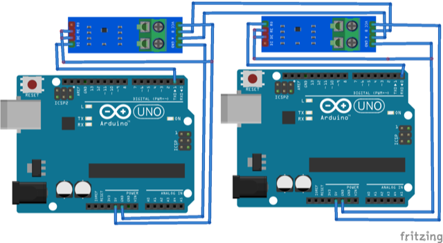
To set up communication between two Arduino boards using Modbus RTU and the Arduino Modbus library, first connect the two Arduino boards using an RS485 transceiver. You’ll need a pair of RS485 transceivers — one to configure an Arduino as a Modbus client and the other to configure another Arduino as the Modbus server.
- To configure the first Arduino board as a Modbus transmitter, connect the RE and DE pins of the module to 5V and connect the DI pin of the module to Arduino’s TX pin.
- To configure the other Arduino board as a Modbus receiver, connect the RE and DE pins of the module to Ground and connect the RO pin of the module to Arduino’s RX pin.
- Next, connect the 5V and ground pins of both modules with the 5V out and GND of the respective Arduino(s). Then, connect the Data B and Data A pins of one module with the Data B and Data A pins of the other module.
The circuit connections are shown below.
Upload the following sketch to Arduino configured as Modbus transmitter.
#include “ArduinoModbus.h”
ArduinoModbus master;
void setup() {
Serial.begin(9600);
master.begin();
}
void loop() {
// Send a Modbus read request to slave address 1 and read 10 registers starting from register address 0
int response = master.read(1, 0, 10);
// Check the response
if (response == 0) {
// The request was successful, Get the read values from the response buffer
uint16_t values[10];
master.getResponseBuffer(values, 10);
// Do something with the read values
Serial.println(“Read values:”);
for (int i = 0; i < 10; i++) {
Serial.print(values[i]);
Serial.print(” “);
}
Serial.println();
}
else {
// The request failed
Serial.println(“Read request failed”);
}
// Wait for 1 second before sending the next request
delay(1000);
}
Upload the following sketch to Arduino configured as the Modbus receiver.
#include “ArduinoModbus.h”
ArduinoModbus slave(1);
void setup() {
// Set up serial communication
Serial.begin(9600);
// Initialize the Modbus slave
slave.begin();
}
void loop() {
// Check for incoming Modbus requests
int request = slave.available();
// If there is a request, process it
if (request > 0) {
// Get the request type
byte type = slave.getRequestType(request);
// If the request is a read request, send the read values to the master
if (type == MODBUS_READ) {
// Get the register address and number of registers to read
word address = slave.getRequestAddress(request);
byte count = slave.getRequestCount(request);
// Read the registers from the Arduino’s memory
uint16_t values[count];
for (int i = 0; i < count; i++) {
values[i] = slave.readRegister(address + i);
}
// Send the read values to the master
slave.sendResponse(request, values, count);
}
}
}
You can observe the values transmitted between two Arduino(s) on Arduino IDE’s Serial Monitor by connecting either Arduino to a computer.
Arduino Modbus TCP example
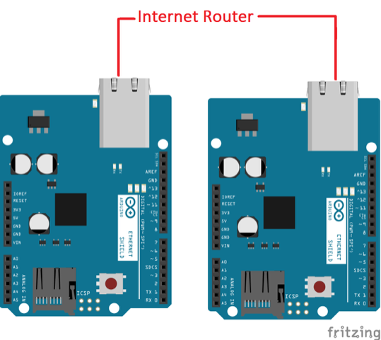
To set up communication between the two Arduino boards using the Modbus TCP and the Arduino Modbus library, install Ethernet shields on the two boards and connect both Arduinos to the same network through the Ethernet cables or a WiFi connection.
Upload the following sketch to Arduino configured as a Modbus transmitter.
#include “ArduinoModbus.h”
ArduinoModbus master;
void setup() {
// Set up serial communication
Serial.begin(9600);
// Connect to the slave Arduino board at IP address of your network
master.connect(“IP_ADDRESS”);
}
void loop() {
// Send a Modbus read request to slave address 1 and read 10 registers starting from register address 0
int response = master.read(1, 0, 10);
// Check the response
if (response == 0) {
// The request was successful
// Get the read values from the response buffer
uint16_t values[10];
master.getResponseBuffer(values, 10);
// Do something with the read values
Serial.println(“Read values:”);
for (int i = 0; i < 10; i++) {
Serial.print(values[i]);
Serial.print(” “);
}
Serial.println();
} else {
// The request failed
Serial.println(“Read request failed”);
}
// Wait for 1 second before sending the next request
delay(1000);
}
Upload the following sketch to Arduino configured as a Modbus receiver.
#include “ArduinoModbus.h”
ArduinoModbus slave(1);
void setup() {
// Set up serial communication
Serial.begin(9600);
// Start the Modbus server
slave.beginServer();
}
void loop() {
// Check for incoming Modbus requests
int request = slave.available();
// If there is a request, process it
if (request > 0) {
// Get the request type
byte type = slave.getRequestType(request);
// If the request is a read request, send the read values to the master
if (type == MODBUS_READ) {
// Get the register address and number of registers to read
word address = slave.getRequestAddress(request);
byte count = slave.getRequestCount(request);
// Read the registers from the Arduino’s memory
uint16_t values[count];
for (int i = 0; i < count; i++) {
values[i] = slave.readRegister(address + i);
}
// Send the read values to the master
slave.sendResponse(request, values, count);
}
}
}
You can observe the values transmitted between the two Arduino boards on Arduino IDE’s Serial Monitor by connecting either board to a computer.
You may also like:


Filed Under: Networking, Tutorials
Log in to leave a comment:
Lost your password?
Don't have an account? Register here