In many applications it is required to precisely control speed of DC motor to an exact RPM. In such application it is required to control as well as measure DC motor speed. In close loop control system speed of DC motor is controlled at the same time its actual speed is also measured and given as feedback. The system compares require speed and actual speed and takes necessary action if deviation is found. So simultaneously DC motor speed is increased or decreased by applying PWM and its actual speed is measured means two tasks are performed simultaneously, generating PWM and measuring RPM.
Here the given project does the same. It generates PWM to vary speed of DC motor and at the same time it continuously measures RPM of it. The project is built using AVR micro controller ATMega16. It increases pulse width from 10% to 99% and measures DC motor RPM and displays pulse width as well as RPS (revolution per second) on LCD.
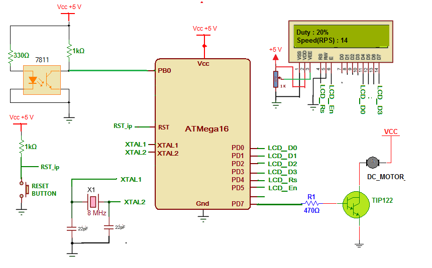
Circuit diagram:
As shown in figure circuit is built using AVR ATMega16, 16×2 LCD, darlington NPN transistor TIP122, opto interrupt sensor MOC7811 and few additional components.
-
The internal IR LED of MOC7811 is forward biased by giving direct 5 V supply through 330E current limiting resistor. The photo transistor is connected in switch configuration. The output of sensor is taken from collector of photo transistor
-
This output is given to timer/counter 0 input pin PB0 of ATMega16
-
The LCD is connected to PORTD in 4-bit mode. Its data pins D4-D7 are connected to PD0 – PD3 and control pins Rs and En are connected to PD4 and PD5 respectively. RW pin is connected to ground to make write enable. 1 K pot is connected to brightness control pin VEE to vary LCD brightness
-
The PWM output pin PD7 is given at the input of TIP122 through limiting resistor 470E. DC motor is connected to collector output of TIP122 as shown. Thus PD7 pin drives DC motor through TIP122
-
A crystal (8 MHz) is connected to crystal input pins along with two 22 pF capacitors. It will provide clock signal for all micro controller internal operations
-
A reset push button is connected to reset input pin to provide manual reset to controller
Circuit working and operation:
-
Initially motor is at rest. A strip is attached to motor shaft such that as motor rotates the strip passes through the gap of MOC7811. So this will generate a pulse. So revolution of motor is converted into pulse
-
The micro controller starts generating PWM on PD7 pin. The duty – pulse width increases from 10% to 99% and again it reduces to 10% and this cycle continuous.
-
Micro controller sets 10% pulse width, display it on LCD and apply it to motor. The motor starts rotating slowly. Then it waits for 2-3 seconds for motor to settle down to new speed.
-
Then micro controller starts counting pulses coming from sensor and counts it for 1 sec only. After 1 sec It directly displays the pulse count as RPS on LCD
-
Then it waits for 2-3 sec. Again it increases pulse width to 20% and display it. Wait for motor to attain stable speed and measures the pulse count. After 1 sec updates the pulse count as new RPS (speed).
-
Again after 2-3 second the cycle repeats. Every time the pulse width is increased in step of 10% and new RPS is displayed.
-
The pulse width is increased upto 99% and after that once again it is reduced to 10% and whole cycle repeats continuously
-
So micro controller continuously increases motor speed by generating PWM and also counts RPS and display them on LCD
Above working is based on the program embedded into internal FLASH (memory) of ATmega16 micro controller
Software program:
The program is written in C language. It is compiled using AVR studio software tool. It is simulated using AVR simulator 2 for ATmega16 device available with AVR studio software. Here is the C program code

Fig. 1: Prototype of AVR ATMega16 based DC Motor Speed Control Circuit designed on breadboard
Project Source Code
###
#include <avr/io.h>
#include<string.h>
#include <util/delay.h>
unsigned int duty_cycle=25,duty=10;
void senddata(unsigned char data)
{
_delay_ms(2);
unsigned char d;
d = data & 0xF0;
PORTD |= 0x10;
PORTD = (0x10) | (d>>4);
PORTD |= 0x20;
PORTD &= 0xDF;
d= data & 0x0F;
PORTD = (0x10) | d;
PORTD |= 0x20;
PORTD &= 0xDF;
}
void sendcmd(unsigned char cmd)
{
_delay_ms(2);
unsigned char d;
d = cmd & 0xF0;
PORTD &= 0xEF;
PORTD = d>>4;
PORTD |= 0x20;
PORTD &= 0xDF;
d= cmd & 0x0F;
PORTD = d;
PORTD |= 0x20;
PORTD &= 0xDF;
}
void printstr(char *s)
{
uint8_t l,i;
l = strlen(s); // get the length of string
for(i=0;i<l;i++)
{
senddata(*s); // write every char one by one
s++;
}
}
void lcd_init()
{
sendcmd(0x02);
sendcmd(0x28);
sendcmd(0x0E);
sendcmd(0x01);
printstr("Duty:");
sendcmd(0xC0);
printstr("Speed(RPS):");
}
void display_duty(unsigned int duty)
{
unsigned int d;
unsigned char ascii[2];
d=duty%10;
ascii[1]=d+0x30;
duty=duty/10;
ascii[0]=duty+0x30;
sendcmd(0x85);
senddata(ascii[0]);
senddata(ascii[1]);
senddata('%');
}
void display_rps_value()
{
unsigned int t1,a,t;
unsigned char asci[3];
unsigned char tmp1,tmp2;
tmp1 = (TCNT0 & 0x0F);
tmp2 = TCNT0 & 0xF0;
tmp2 = tmp2>>4;
t = tmp1+tmp2*16;
if(t>=100)
{
a=2;
while(t>=10)
{
t1=t%10;
asci[a]=t1+0x30;
t=t/10;
a--;
}
asci[0]=t+0x30;
}
else
{
t1=t%10;
asci[2]=t1+0x30;
t=t/10;
asci[1]=t+0x30;
asci[0]=0x20;
}
sendcmd(0xCB);
senddata(asci[0]);
senddata(asci[1]);
senddata(asci[2]);
}
int main(void)
{
DDRD = 0xFF;
DDRB = 0x00;
PORTD = 0x00;
TCCR2=0x6B;
lcd_init();
while(1)
{
display_duty(duty);
OCR2 = duty_cycle;
_delay_ms(2500);
TCNT0 = 0x00;
TCCR0 = 0x06;
_delay_ms(1000);
TCCR0 = 0x00;
display_rps_value();
_delay_ms(2500);
if(duty_cycle<250) {duty_cycle+=25;duty+=10;}
else if(duty_cycle==250) {duty_cycle=25;duty=10;}
if(duty==100) duty-=1;
}
}###
Circuit Diagrams
Project Video
Filed Under: Electronic Projects
Filed Under: Electronic Projects

Questions related to this article?
👉Ask and discuss on EDAboard.com and Electro-Tech-Online.com forums.
Tell Us What You Think!!
You must be logged in to post a comment.