BPSK Modulation using GNU Radio and NI USRP-2920
Requirements:
-
Laptop(preferably with Ubuntu)
-
GNURadio 3.7.7.1
-
SMA cable
-
USRP 2920
Summary:
BPSK stands for binary phase shift keying. In this kind of modulation scheme, data bits are mapped to the phase of carrier frequency and these two are separated from each other by 180 degrees.
In this implementation I am going to map 0’s and 1’s to pi and 0 and then add them to the phase of carrier frequencyOne can view adding 0 and pi to the phase of the carrier wave, same as changing its direction without changing its magnitude.
Here I am using an SDR which is gnuradio 3.7.7.1 with NI USRP 2920. As gnuradio is very fast developing platform hence this version is very important to avoid compatibility issues.

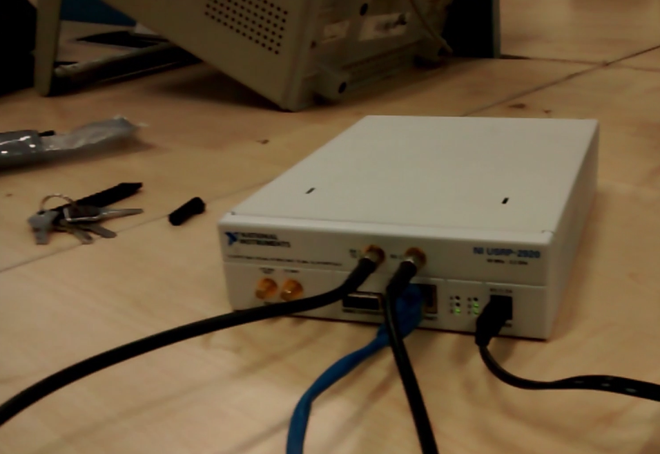
Fig. 1: Image showing USRP-2920 Cable Connections
Description:
Transmitter
First connect USRP from your laptop then time uhd_fft in your terminal. If a window pops up showing noise in graphical manner then it’s successfully connected.
If not then, try this video.
Then in order to interface USRP with gnuradio you would need to flash your NI USRP with correct image accordingly for which you can follow this link.
After USRP gets detected by GNURadio, make a simple block diagram in GRC for PSK transmitter random source.

Fig. 2: Block Diagram of GRC used for PSK Transmission
Random source generates 0’s and 1’s which are converted to float.
Then to map these 0’s and 1’s to -1’s and 1’s respectively multiply it with 2 then add -1.
([0 1] * 2) – 1 gives us -1 or +1
Now feed the output in QT GUI sink block, where you’ll see two dots at -1 and1 on IQ-plo, same as one would expect from BPSK transmitter.

Fig. 3: Graph showing Phase Modulation over BPSK
Now, connect the URSP sink blocks and replace the random source with file source containing desired symbols. In this project I’m using a file containing a’s and b’s whose ascii value in decimal number system are 97 and 98 respectively.

Fig. 4: Block Diagram of USRP
Receiver:

Fig. 5: Block Diagram of USRP Receiver
Now on the receiver side, one would expect to receive +1 and -1 from USRP source but there is always a channel impulse response and channel noise (as SMA cable is being used therefore noise is AWGN noise). Now to equalize the channel impulse response and to get an estimate of the received signal, CMA equalizer (CMA – constant modulus algorithm) is used.
Output of CMA equalizer tries to estimate the incoming signal, hence initially reception is noisy but it stabilizes after a few seconds.
To get more definitive reception, a threshold block is added and is set in such a way that the output transitions from 0.0 to 1.0 when the input signal transitions from below to above high level (0.1 in this case). The output transitions from -1.0 to 0.0 when the input signal transitions from above to below Low Level(-0.1 in this case).
To store them into a file, just add 97 (to get a’s and b’s) and convert them back to unsigned characters and send them to a file sink.

Fig. 6: Graph showing Phase Modulation after BPSK
Here the IQ-plot of receiver output from CMA equalizer is given in Red and output from threshold block is given in Blue.
Project Video
Filed Under: Electronic Projects
Filed Under: Electronic Projects


Questions related to this article?
👉Ask and discuss on Electro-Tech-Online.com and EDAboard.com forums.
Tell Us What You Think!!
You must be logged in to post a comment.