This project tries to analyse the different methods in which theft can occur and hence find appropriate solutions for the same. Moreover the cost is also a factor and that is kept in mind. This project is trying to integrate preventive as well as curative methods for vehicle theft in India.

The design consists of a digital code lock which comprises of a Digital key pad with an LCD which will be used for entering the Passwords (10 Keys 5 Digit) to enable the ignition to start the vehicle. Without the correct combination of the password the car is not supposed to start ideally.
This car will also be fitted with a GSM MODEM with an ability to send and receive SMS. In case there is a trial to break the password or bypass it, the system will take an action to send an SMS to the original user. In case the original user feels that the car might be stolen, then in the response to the alert message, the original user can reply with an SMS to the car informing it that it has indeed being stolen and it should take actions to prevent it from being stolen.
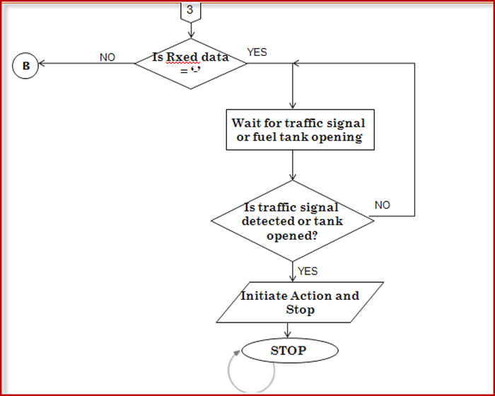
A GPS is also interfaced to the system, so that when the car comes to know it is being stolen, it will retrieve GPS co-ordinates and SMS it to the number stored in car’s PC (owner’s phone number). Meanwhile, the car will wait till it encounters a traffic red light. The signals being continuously transmitted by the traffic post is received by the car and at this time the car will internally lock the doors, stop the car (auto-jamming of brakes) and initiate an audio-visual alarm. Also if the thief is smart enough to avoid traffic signals, the car will wait for another opportunity at a petrol bunk. The vehicle’s fuel tank is attached with a switch, such that when tank lid is opened, it senses it and initiates audio-visual alarm and locks doors from inside. The GPS sends co-ordinates to the microcontroller in the car, which in turn gives it to the GSM and that will SMS it to owner. This information transfer happens every two minutes once car is stolen.
If car is stolen by towing, then also the car senses it through the Vehicle Lift sensor (which is nothing but an IR sensor) and again takes the same actions as previously stated to prevent theft and nab the culprit.
Apart from the security system, the Smart is also fitted with a timer device which will keep on looking for the time and data and can remind us of important dates and appointments. Automatic Reminders in the vehicle will be housed in a PC and will compare with the current date from the PC and can raise the alarms and remind the owner of details like: Expiry of License, Expiry of insurance, Next service due date etc. The values in the EEPROM will be sent from the PC using RS232 protocol and a Micro-controller.
The car also features an intelligent braking system based on proximity. The car is able to detect any obstacle in front of it (using IR sensor) and sends this information the microcontroller which will send a signal to the DC motor to stop the wheels of car.
Below is the block diagram of the smart car prototype which will be designed as part of this project.
Block Diagram of Smart Vehicle

Methodology
DESIGN METHODOLOGY- SECTIONAL DESCRIPTION
GPS 634R from NSK electronics is being used. This was considered mainly because of its size (32mmX32mmX8mm). It’s easy to mount on the car and can be well hidden from the thief. Moreover, it has highest tracking sensitivity (161 dBm) as compared to other GPS models. Also, the GPS unit operates at 5V in this project (same as microcontroller).
The Password Code Lock System.
The main purpose of the code lock is to provide a secure user-car interface. The password code lock is a combination of a 16×2 LCD and a 5×5 matrix keypad. These two are interfaced to the AT89C51. Commands are sent from the AT89C51 to the LCD as to what it should display. At the outset, the LCD is made to display “Smart car with Theft Protection” in two rows. To start the car, the correct password needs to be entered.
Now, a signal needs to be sent to the microcontroller that password is going to be entered (here, polling is used to identify password entry enabling). This function is performed by Switch 12 in the keypad. The user is to press SW12 down for a while (2 seconds). This results in the microcontroller taking action in terms of asking the user to enter the password. “Enter Password” is displayed on the first row of LCD. The user is supposed to press the 5 digit password in the keypad. The password characters are displayed as * on the second row of the LCD. The user is given 3 trials to enter the correct password, failing which the car will be locked and all its functions disabled.
It needs to be highlighted here that after the microcontroller accepts the password, it sends it on the UART to the PC. The correct password is stored in the PC and not in the AT89C51. Being in the PC allows the user to change the password at his will. This might raise security issues, the question being what if the thief alters the password. The software is intended to be protected against means of hacking and only the user will be given means to access the internal software. Better still; the manufacturer of the security system can change it for him. This flexibility of allowing the user to change his password is given, again, due to security issues. Suppose the password is stored in the hardware (microcontroller) and somehow, somebody comes to know of the password. Now the user is aware that somebody knows his password, then he will not be able to change it (since the hardware will be hidden somewhere inside the car) and his car will be at risk. On the other hand, in the case of this project, the PC is external and accessible, hence allowing the user to change the password at will.
The Wireless Transmitter and Receiver section
The idea is to mount the receiver on the smart car, and the transmitter on all the traffic signal posts.. They work at Radio frequency and use ASK modulation for their output waves.
Petrol Lid Sensor
The petrol Lid sensor is a SPST (single pole single throw) switch. One end of the switch is connected to P3.5 of AT89C51 as well as Vcc and the other end to the GND. The switch is initially closed, which indicates the petrol tank lid is closed. When the message is given by the owner to the car to Stop vehicle, this pin P3.5 is being polled by the microcontroller. When the switch is opened, this pin is pulled to Low(GND) which causes the microcontroller to take action, i.e. initiate audio-visual alarm and suspend all the car functionalities. This is one method of trying to draw attention to the stolen vehicle.
Audio Visual Alarm Section
In the project prototype, a standard 16×2 LCD is used to represent the visual alarm, which in reality could be a more advanced dot matrix LCD. The audio alarm is a pre-recorded message “Car is Stolen” which is stored on the PC in the car. The visual alarm (LCD) is brought into action by the microcontroller, while the audio alarm is initiated by the VB program running on the PC.
This LCD is interfaced with the microcontroller unit and is in continuous write mode, i.e., microcontroller alone will write to LCD and not vice-versa (R/W is grounded). It shares its data pins with the first LCD. Thus its data pins D7-D4 are also connected to P1.4-P1.7. The limited controller pins prompted this design. It is only the Enable signal or R/S signal which decide whether the LCD has to display anything or not. So, these signals are sent on different pins. EN of this LCD is connected to P1.0 and the R/S signal is connected to P1.1. When we want this LCD to display something, a different function is called which sends a high-low signal on this LCD’s Enable pin.
The information to be displayed is stored in the AT89C51 and will be sent to the LCD whenever it receives the appropriate signal. When car is indicated as stolen, the car is in polling; it is waiting either for traffic signal or the opening of the petrol lid. On event of any of these two actions, the LCD will display “Car Stolen” on the first row and “Initiating Action” on the second row. Simultaneously, an audio alarm repeating the words “car is stolen” begins to play. The audio alarm can play through the radio or stereo speakers present in the car.
Wheel control section
Wheel control section
This project considers 4-wheeled vehicles. For the prototype, small rubber tyres, about 4 inches in diameter, are used. The DC motor is responsible of controlling the wheels of the car. 100 rpm 12V DC motor with gearbox was best suited for the prototype.
In the project, the DC motor is connected to two relays which control its rear coils. The wheel base is such that control of the rear wheels also controls movement of car. The front wheels are always free to move (front & back direction), but the rear wheels move only in the forward direction or they brake (don’t move). The two relays tell the DC motor when to rotate and when to stop, hence moving the car forward or stopping it. The obstacle detecting sensor is connected to another relay which is also directly connected to the DC motor.
As seen in figure below, there are two relays controlling the DC motor. The motion switch is placed at the Common pin of second relay so that it gives control of the car’s movement (switching it ON alone will make the car move forward, otherwise car remains stationary), otherwise every time the ignition is enabled, the car would uncontrollably move forward and would be problematic for testing purposes. The ULN2003A drives the high-current rated relays. Since the ULN2003 is a voltage inverter also, the commands issued by the microcontroller should be reversed.

Relay 1 is connected to P0.0 and relay 2 is connected to P0.1 of AT89C51 through a ULN2003a. P0.0 is given the name car_rear_coil1 and P0.1 is given the name car_rear_coil2 in the program. Control of the relays is done by controlling the output from P0.0. The output of relay 1 is fed to relay 2, so the movement of Dc motor fully depends on relay1 only. Relay 1 acts like a switch of relay2 while relay2 acts like a switch of DC motor.
The third relay is used to control the central locking system. Here, the central locking system is just represented by two LED’s. A red LED indicates that the car is internally locked, while the green LED indicates that the car is ready to be driven. The relay, on signals from the microcontroller, lights up the appropriate LED.
Result Analysis
HARDWARE RESULTS


This prototype was designed to be flexible for experimenting. The PC is outside the car and is powered by a mains supply, but in a real car, there will be changes in these areas. The microcontroller board is placed centrally while other components are interfaced and placed around it. The wheels of this prototype actually propel the car forward when ignition is enabled. The following snapshots give part-by-part labelling of the designed car.

Part-by-part labelling of Smart Car hardware

Other parts of the Smart Car
There are other hardware modules which are connected to the smart car externally; The GSM module and the wireless transmitter circuit (which is not connected to the car, but placed at a distance).

(a) Wireless Transmitter circuit on a separate PCB
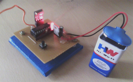
(b) Wireless Tx when connected to battery (LED glows to indicate power)

the GSM module used in project.
When the project is in progress, the various components are switched ON and work according to the code burned into the ROM of the AT89C51.

(a)- Smart Car just powered On, (b)- Smart Car when pass
and centrally locked (red LED) word entered and ignition enabled(green)
Software Result
As a means of implementing this project, VB version 6.0 forms an integral part. This front end GUI is meant to be actually implemented in real cars also and is not just meant for debugging or simulating this project. This software is as much a part of this project as is the hardware. It is through commands in this software program that the hardware responds. Thus, the following snapshots are a result of running the entire project, with all the hardware connections powered up, interfacing to PC made and external modules connected as required.

Front End VB design to be used in project.
The SEND MESSAGE box is meant for recording the messages sent to the number entered in the slot provided. GET MESSAGE box displays the SMSses received by the Smart car (GSM). The following snapshots capture different stages in the running of the project. It is a brief way to validate that the required output has been achieved.
-opened-and-ready-for-experimentation..jpg)
All communication ports (GSM, GPS & 8051 UART) opened and ready for experimentation.
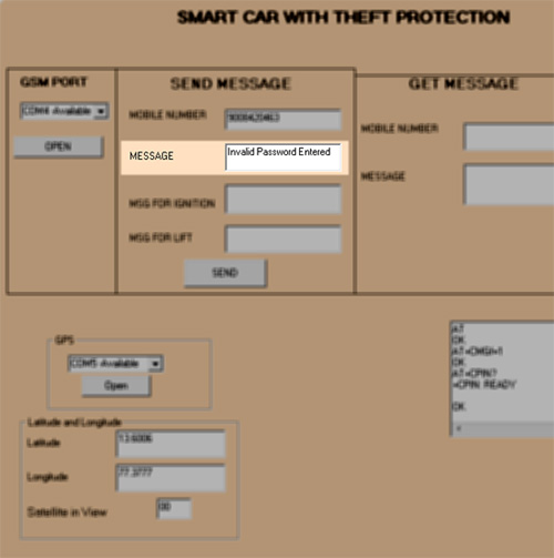
“Invalid Password” SMS sent to user, when wrong password entered
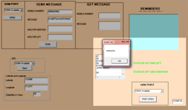
“Welcome” SMS to be sent to user, as password entered in hardware is right.

SMS to be sent as Ignition on hardware has been enabled.
Here, the ‘send’ box is only for debugging purpose. The appearance of this box will tell us when the SMS will be sent, and by clicking on the box, the SMS is sent and the process can continue. In reality, the appearance of the command boxes will be removed and SMS sending will be automatic.
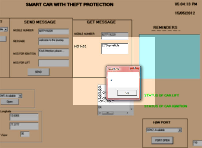
A “Stop vehicle” message comes from user. Click OK to initiate action.
When the owner sends STOP SMS to his car, the car will now wait for a traffic signal or opening of petrol lid. Once done, the alarm is heard playing in the background and the alert being displayed on the LCD.
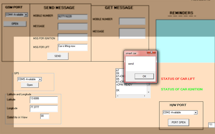
A case of car lifting. A message “Car is lifting now” to be sent to owner.
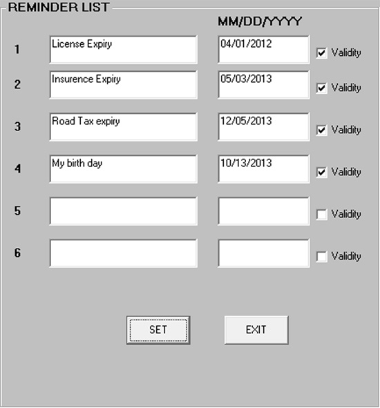
The Reminders List provided by Smart Car. Dates to be set here.
.jpg)
Reminders Box alerting owner about different dates (expired & yet to expire)
Annexures
[A]. COMPONENT LIST
i. AT89C51
ii. SIM300 GSM module on GSM board
iii. 16×2 LCD (2 nos.)
iv. 5×5 matrix keypad
v. GPS-634R
vi. DC Motor (with gear box)
vii. LeONE Relays (4 nos.)
viii. TLP434, RLP434
ix. HT12E, HT12D
x. 7805 regulator (2 nos)
xi. MAX232
xii. ULN2003A
xiii. LEDs (5 nos)
xiv. Resistors (1k?, 10k?, 4.7k SIP stick, 10?, 47k?)
xv. Capacitors (10uf, 33uf, 12pf)
xvi. 5V battery
xvii. Transformer
xviii. DB9 connector (3 nos.)
xix. Reset switches (3 nos)
xx. Toggle switches (2 nos)
xxi. IR sensors (2 nos)
xxii. SMPS (1 no.)
xxiii. Wires as required
[B].PROGRAM CODE FLOWCHART


Video
Video
Project Source Code
Circuit Diagrams

Filed Under: Electronic Projects

Questions related to this article?
👉Ask and discuss on EDAboard.com and Electro-Tech-Online.com forums.
Tell Us What You Think!!
You must be logged in to post a comment.