Real Time Clock (RTC) is used to store Time and Date in the system even when the system is not in operation. This is the system used in many devices including Laptop. Mobile phones, Tablet, Digital Cameras etc. RTC is inbuilt part of any electronics device. DS1307 is widely used RTC which we can interface with any controller. Many controllers now has inbuilt RTC to store timing information. In this article, we will learn how to configure inbuilt RTC of controller LPC 2148.

Fig. 1: Digital Clock Using Inbuilt RTC of LPC2148 Prototype
Real Time Clock (RTC) is used to store Time and Date in the system even when the system is not in operation. This is the system used in many devices including Laptop. Mobile phones, Tablet, Digital Cameras etc. RTC is inbuilt part of any electronics device. DS1307 is widely used RTC which we can interface with any controller. Many controllers now has inbuilt RTC to store timing information. In this article, we will learn how to configure inbuilt RTC of controller LPC 2148.
LPC 2148 has inbuilt RTC which can be configured as needed. For this we have to configure the various registers of LPC 2148 architecture. Features of inbuilt RTC of LPC 2148 are as follows.
· Measures the time to maintain a calendar and clock.
· Ultra Low Power design to support battery powered systems.
· Provides Seconds, Minutes, Hours, Day of Month, Month, Year, Day of Week, and Day of Year.
· Dedicated 32 kHz oscillator or programmable pre-scalar from VPB clock.
· Dedicated power supply pin can be connected to a battery or to the main 3.3 V.
RTC has 3 dedicated pins.

Fig. 2: Pin Numbers of RTC in LPC1768
Registers for RTC can be divided into four categories mentioned below.
a. Miscellaneous Register Group
b. Time Counter Group
c. Alarm Register Group
d. Reference Clock Divider
1. Miscellaneous Type of registers:
This group of register contains few miscellaneous registers which are used for functions like ILR, CTCR, CCR, CIIR, AMR, CTIME, CTIME0, CTIME1 and CTIME2. Functions of each registers are as follows.
ILR – Interrupt location register
The Interrupt Location Register is a 2-bit register. Whenever interrupt occurs from RTC, this register specifies which blocks are generating an interrupt.
CTCR – Clock Tick Counter register (CCR)
The Clock Tick Counter is read only. It can be reset to zero through the Clock Control Register (CCR). The CTC consists of the bits of the clock divider counter
CCR – Clock Control Register
The clock register is a 5-bit register. It is used to control the operation of the clock divide circuit
CIIR – Counter increment interrupt register.
The Counter Increment Interrupt Register (CIIR) gives the ability to generate an interrupt every time a counter is incremented.
AMR – Alarm Mask Register
The Alarm Mask Register (AMR) allows the user to mask any of the alarm registers.
The interrupt will be generated only if the counter comparison first changes from no match to match.
CTIME – Consolidated time register
The values of the Time Counters can optionally be read in a consolidated format which allows the programmer to read all time counters with only three read operations.
CTIME0 – Consolidated time register 0
The Consolidated Time Register 0 contains the low order time values: Seconds, Minutes, Hours, and Day of Week.
CTIME1 – Consolidate Time Register 1
The Consolidate Time register 1 contains the Day of Month, Month, and Year values.
CTIME2 – Consolidate Time Register 2
The Consolidate Time register 2 contains just the Day of Year value.
2. Time Group Register:
The time group of registers contains the following registers.

Fig. 3: Bit Addresses and Description of Time Group Register in LPC1768
3. Alarm Group of Registers:
The alarm group of register contains the following registers:

Fig. 4: Bit Addresses and Description of Alarm Group Register in LPC1768
4. Reference clock divisor register:
The reference clock divider (referred to as the prescaler) allows generation of a 32.768 kHz reference clock from any peripheral clock frequency greater than or equal to 65.536 kHz (2 × 32.768 kHz). This permits the RTC to always run at the proper rate regardless of the peripheral clock rate.
Basically, the Prescaler divides the peripheral clock (PCLK) by a value which contains both an integer portion and a fractional portion. The result is not a continuous output at a constant frequency, some clock periods will be one PCLK longer than others. However, the overall result can always be 32,768 counts per second.
The reference clock divider consists of a 13-bit integer counter and a 15-bit fractional counter.
The reference clock divisor register contains the following registers.
PREINT: Prescalar Integer Register.
PREINT = int (PCLK / 32768) ? 1.
PREFRAC: Prescalar fractional register:
PREFRAC = PCLK ? ((PREINT + 1) × 32768).
4. Operation:
The basic operation of the On-chip RTC can be divided into three steps as shown below:
a. RTC Configuration:
Registers responsible for RTC configuration:

Fig. 5: Registers for RTC Configuration
Clock Source Configuration:
The foremost thing to be done in order to configure the RTC is to select the clock source for the RTC.
The RTC is supported with two types of clock sources. They are the external oscillator and an internal pre-scalar clock respectively.

Fig. 6: Block Diagram to select clock source for RTC Configuration
The RTC clock can be selected by updating the CLKSRC bit in the CCR register. If the internal prescalar is selected, then the PREINT and PREFRAC register values must be calculated and must be updated. The PREINT and PREFRAC values can be calculated as below:
PREINT = int (PCLK / 32768) ? 1.
PREFRAC = PCLK ? ((PREINT + 1) × 32768).
Once the clock source is selected, the RTC must be reset by setting the CLCRST bit in the CCR register.
Time Configuration:
The time of the RTC clock has to be configured once the RTC clock source is configured.
The RTC time can be configured by updating the Time counter registers with the appropriate register values.
The RTC also features an alarm facility. The alarm registers may also be updated if we want to set the alarm, at this point.
b. Enable RTC:

Fig. 7: Registers to use inbuilt RTC in LPC2148
The RTC can be enabled by setting the CLKEN bit in the CCR register.
c. Reading RTC:
The RTC time registers are updated along with the pulse provided by the RTC Source clock.
These registers may be read at regular intervals in order to update the system with the current time and execute any process accordingly.
Project Source Code
###


//Program to Configure RTC


 #include<lpc21xx.h>

 #include"lcd4bit.h"


unsigned char flag=0;


void rtc_int(void)__irq{

ILR = 0X01;

flag = 1;

VICVectAddr = 0X00000000;

}


void init_rtc(){

ILR = 0X01;

CCR  = 0X13;

CCR =  0X11;

CIIR = 0X01;

SEC = 0X00;

HOUR =0X00;

MIN = 0X00;

VICIntEnable = 0x00002000;

VICVectCntl0 = 0x0000002D;

VICVectAddr0 = (unsigned)rtc_int;

}


int main(void){

init_lcd();

init_rtc();

while(1){

if(flag){

lcd_command(0x80);

flag=0;

lcd_data(HOUR/10 + '0');

lcd_data(HOUR%10 + '0');

lcd_data(':') ;

lcd_data(MIN/10 + '0');

lcd_data(MIN%10 + '0');

lcd_data(':') ;

lcd_data(SEC/10 + '0');

lcd_data(SEC%10 + '0');

}

  }

}


###
Project Source Code
### //Program to Interface LCD #include <LPC21xx.h> #include "lcd4bit.h" void Delay(unsigned long b){ while (--b!=0); } void write_command(int cmd) { IO1CLR |= 0x00f00000; /* Clear D4-D7 */ IO1CLR |= 0x00040000; /* Read/Write = 0 */ IO1CLR |= 0X00020000; /* Register Select = 0,Command */ IO1SET |= 0x00f00000 & cmd; /* Set D4-D7 */ IO1SET |= 0X00080000; /* Enable = 1 */ Delay(30000); IO1CLR |= 0x00080000; /* set E to low */ } void write_data(int dat) { IO1CLR |= 0x00f00000; /* Clear D4-D7 */ IO1CLR |= 0x00040000; /* Read/Write = 0 */ IO1SET |= 0X00020000; /* Register Select = 1,Data */ IO1SET |= 0x00f00000 & dat; /* Set D4-D7 */ IO1SET |= 0X00080000; /* Enable = 1 */ Delay(30000); //delay ~2ms IO1CLR |= 0x00080000; /* Set E to low */ } void lcd_data(char dat){ write_data(dat << 16); write_data(dat << 20); } void lcd_command(char cmd){ write_command(cmd << 16); write_command(cmd << 20); } void printlcd(char *CPtr){ while(*CPtr != '�') { lcd_data(*CPtr); CPtr++; Delay(20000); } } void init_lcd(void) { IO1DIR |= 0x00FE0000; Delay(200000) ; write_command(0x30 << 16); Delay(100000); write_command(0x30 << 16); Delay(100000); write_command(0x30 << 16); Delay(100000); write_command(0x20 << 16); lcd_command(0x01); /* clear display */ lcd_command(0x06); /* auto address inc */ lcd_command(0x0c); /* cursor off */ lcd_command(0x80); /* first location */ } ###
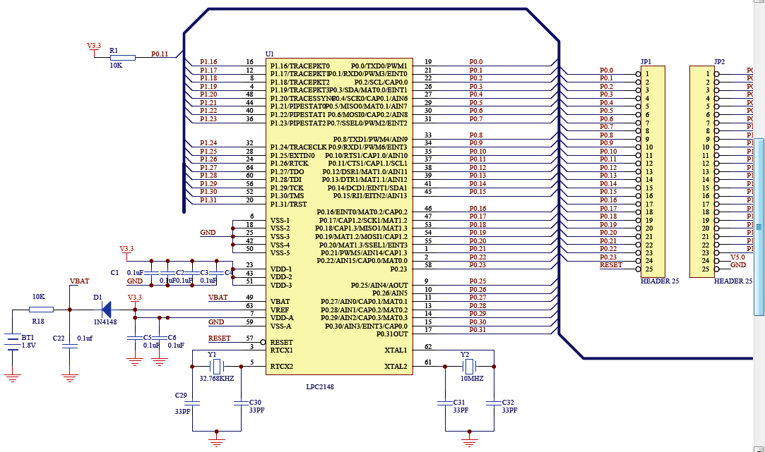
Circuit Diagrams
Project Video
Filed Under: ARM.
Filed Under: ARM.

Questions related to this article?
👉Ask and discuss on EDAboard.com and Electro-Tech-Online.com forums.
Tell Us What You Think!!
You must be logged in to post a comment.