When using MOSFET as a switch, it can be connected in two switching modes – high side switch and low side switch. Contrary to low side, the high side configuration of MOSFET requires some external circuitry to turn it ON. There are various methods for driving the high side MOSFET. The following three methods are most commonly used to drive a MOSFET as high side switch –
1. Dual power supply method
2. Gate Driver IC method
3. Bootstrap circuitry method
The High and Low side switching of a MOSFET has been already discussed in the following tutorial –
High and Low Side Switching of MOSFET
The use of IR2110 Gate Driver IC has also been discussed in the same tutorial. Now, in this tutorial, Bootstrap Circuit method to drive a high side MOSFET will be discussed.
Components Required –

Fig. 1: List of components required for High Side MOSFET Bootstrap Drive
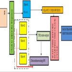
Block Diagram –

Fig. 2: Block Diagram of High Side MOSFET Bootstrap Driver
Circuit Connections –
A MOSFET Q1 is taken which is connected as a high side switch with reference to the load RL. For driving the MOSFET, a bootstrap circuit is connected at the load of the MOSFET. The bootstrap circuit is a capacitor connected at the gate of the MOSFET. This capacitor is represented as C1 in the circuit diagram. The bootstrap capacitor requires a PWM signal to turn on the MOSFET. The PWM signal is generated from an Arduino board. For proving PWM signal, bootstrap capacitor is connected to the output of an optocoupler (Shown as opt1 in the circuit diagram) which receives PWM by connecting its input pin to the pin 2 of the Arduino. Another PWM signal is required at the gate of the gate of the MOSFET. The signal is received through the output of another optocoupler (Shown as opt2 in the circuit diagram) which receives PWM by connecting its input pin to the pin 3 of the Arduino.
While assembling the circuit, following precautions must be taken care of –
1. The input power supply to the gate must be greater than or equal to the threshold voltage (Vgs(the)) of the MOSFET otherwise, it will not turn ON the MOSFET. For this refer to the datasheet of the MOSFET used.
2. Do not exceed the input voltage (drain voltage and gate voltage) of the MOSFET greater than its breakdown voltage as it can damage the MOSFET.
3. Always use a gate to source resistance to avoid any external noise at the gate and to discharge the parasitic capacitance of the MOSFET. Otherwise, MOSFET can get damaged as this parasitic capacitor will keep on charging and will exceed the limit of the gate to source breakdown voltage.
4. Always use a low value of resistor (10E to 500E) at the gate of the MOSFET. This will solve the problem of ringing (parasitic oscillations) and voltage spike in the MOSFET.
5. The diode D1 should have a low forward voltage drop and should sustain a reverse voltage of 24V. The frequency of the circuit is 0.5Hz so a normal diode having 10ms switching speed can work fine.
6. The capacitor used in the circuit must be of higher voltage rating than the input voltage. Otherwise, the capacitor will start leaking the current due to the excess voltage at its plates and can burst out
7. Make sure all the capacitors should be discharged before working on a DC power supply. For this short the capacitors with a screwdriver wearing insulated gloves.
8. Though in the circuit a bleeder resistor could be present but it takes time to get rid the remnant charge from the capacitor, so it is not connected.
9. Use a resistor at the input of optocoupler MCT2E for limiting the input current. Otherwise high current can damage it. Refer the datasheet of the MCT2E optocoupler for checking its technical specifications.

Fig. 3: Image showing circuit connections of High Side MOSFET Bootstrap Driver
How the circuit works –
The MOSFET (Shown as MOSFET Q1 in the circuit diagram) is connected in high side configuration as the load (Shown as resistance RL) is connected between the source and the ground. This MOSFET cannot be driven by applying a voltage at its gate and drain. It needs an external circuit to turn ON. The MOSFET used in the circuit is IRF840 which requires a gate to source voltage (Vgs) or threshold voltage (Vth) in range from 10 to 12V to fully turn ON. The Bootstrap circuit built using the capacitor C1 and Diode D1 is used to drive this MOSFET. The bootstrap circuit is explicitly shown in the circuit diagram below –

Fig. 4: Circuit Diagram of High Side MOSFET Bootstrap Driver
For isolating the input and output, two optocouplers are used. The isolation is optical as in an optocoupler, the input is a LED (Emitter) and the output is a photo transistor(Detector). The pins 2 and 3 of the optocoupler are the input pins of the LED. The forward voltage of the LED is in between 1.23V to 1.5V. The forward current of the LED must be less than 60 mA. For providing the input logic to the optocoupler a microcontroller is used which generates the PWM signal for this purpose. The microcontroller board used in the circuit is Arduino. The PWM signal is of 5V and the 100E resistance at the input of optocoupler provide a current of 50mA. This resistance saves the optocoupler from high current. The microcontroller generates two PWM signals with a phase difference of 180 degree. So at a time only one of the optocoupler is ON and another one is OFF. The ON time and off time of the optocouplers decides the ON and OFF time of the MOSFET. This time is also used for calculating the value of capacitor used in bootstrap circuit.
The value of the capacitor to be used in bootstrap circuit can be calculated as follow –
The time constant equation for charging the capacitor is
Time constant, T = 5RC
In the above equation capacitor ‘C’ will charge and discharge fully through resistor ‘R’ in a time equal to time constant ‘T’.
In this circuit time constant is assumed to be 1000 ms and resistance for discharge of the capacitor is assumed to be 220E in value. The value of capacitor now derives as follow –
T = 5RC
C = T/5R
C = 1/5*220E
C = 1000uF (approx.)
When the circuit is powered on and PWM signal is applied at the input of both the optocouplers, then initially the first optocoupler Opt1 is OFF for 1s and second one is ON for 1s as per the time period of the PWM signal. The ON and OFF time period of the PWM signal is set in program code of the Arduino board. In this state the capacitor C1 starts charging with diode D1 and load RL. This develops a voltage of 12V across the capacitor C1 and at this time the transistor Q1 is in OFF state as it is not getting sufficient voltage which should be greater than threshold voltage (Vth). So at output, zero volt is obtained.

Fig. 5: Image showing charging of Bootstrap Capacitor
In the next cycle the optocoupler opt1 gets ON for 1s and optocoupler Opt2 remains OFF for 1s. The capacitor C1 now tries to maintain the 12V across it and this raises the source voltage to 12V. This makes the diode D1 reverse biased as its cathode voltage is now 24V for maintaining the 12V across the capacitor. The capacitor C1 now starts discharging through optocoupler Opt2 and the gate of the MOSFET Q1 develops 24V. This makes the Vgs of MOSFET Q1 equal to 12V which is sufficient enough to drive it. So, at output, HIGH logic or 12V is obtained. The capaacitor C1 is called bootstrap capacitor as it boosts up the 12V input signal to 24V for driving the high side MOSFET.

Fig. 6: Image showing discharging of Bootstrap Capacitor
So, the optocoupler Opt1 is used for turning On the MOSFET and optocoupler Opt2 turns OFF the MOSFET. At the output, HIGH and LOW logic is obtained for 1 second alternatively. As the process repeats, a square with 50% duty cycle and 0.5 Hz frequency is obtained at the output.
Programming Guide –
The Arduino board is used for generating the PWM in the circuit. There are two PWM signals generated at pins 2 and 3 of the board with a phase difference of 180 degrees. In the Arduino sketch, first the pins 2 and 3 of the board are configured to digital output using pinMode() function within the setup() function. In the loop() function which is meant to iterate infinitely, the pins 2 and 3 are set to digital logic or LOW and HIGH respectively followed by a delay of 0.5 second. The digital logic at the pins 2 and 3 is reversed after the delay and again a delay of 0.5 second is provided. This generates two PWM signals having a frequency of 0.5 Hz and 50 % duty cycle having a phase difference of 180 degree with respect to each other.

Fig. 7: Screenshot of Arduino Code used for High Side MOSFET Bootstrap Driver
Check out the complete code from the code section.
Testing the circuit –
On observing the output waveform on a cathode ray oscilloscope (CRO), the following voltage waveform is observed –

Fig. 8: Graph showing Output Waveform of High Side MOSFET Switch
The output waveform has a frequency of 0.5 Hz and 50% duty cycle. So, the bootstrap circuit is perfectly working to drive the high side MOSFET. The bootstrap circuit designed here has also certain limitations. The circuit is load dependent. As the bootstrap capacitor charges through the load so, a load which consist of diode or any component which blocks the negative voltage at the output cannot be used. For low frequency, a high value of capacitor is needed in the circuit.
There are also some advantages of this circuit. First, it is a simple circuit built using few components. When such a simple circuit eliminates the requirement of gate driver IC, it reduces the cost of the circuit as well. So, this circuit is not only simple to design, it is also cost effective.
The bootstrap circuit designed in this tutorial can be used in DC to AC converters, induction heating applications and in making a half bride MOSFET circuit.
You may also like:


Project Source Code
//Program to


/* code of bootstrap circuit for driving the high side MOSFET*/


// the setup function runs once when you press reset or power the board

void setup() {

  // initialize digital pin 2 and 3 as an output.

  pinMode(2, OUTPUT);

    pinMode(3, OUTPUT);

}


// the loop function runs over and over again forever

void loop() {

  digitalWrite(2, LOW);     // turn the first Opt1 optocoupler OFF

  digitalWrite(3, HIGH);    // turn the second Opt2 optocoupler ON

  delay(1000);              // wait for 1 second

  digitalWrite(3, LOW);     // turn the second optocoupler OFF

  digitalWrite(2, HIGH);     // turn the first optocoupler ON

 delay(1000);              // wait for 1 second


}
Project Video
Filed Under: Tutorials
Filed Under: Tutorials

Questions related to this article?
👉Ask and discuss on Electro-Tech-Online.com and EDAboard.com forums.
Tell Us What You Think!!
You must be logged in to post a comment.