While designing the UPS circuits, MOSFET were used in the inverter circuits. The MOSFET were used as High side switches in the circuit. For driving the MOSFET in high side configuration, IR2110 gate driver IC was used. IR2110 is a High –Low side Gate Driver IC which is used with power MOSFET and IGBT. A Gate Driver is a specially designed circuit that is used to drive the Gate of MOSFET or IGBT in High Side Switching application. That means when MOSFET/IGBT is used in High side configuration then a Gatedriver IC is need to be used. In this tutorial, some important concepts like the High and Low side Switching of MOSFET, need of Gate Driver circuit and driving methods of High side MOSFETs will be discussed. These concepts will crystal clear the working of MOSFET as a switch and will so justify the use of MOSFET in inverter circuit as switching component.
Introduction to Uninterruptible Power Supply (UPS) and its design (Part – 1/17)
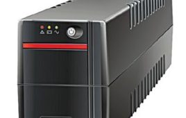
The Uninterruptible Power Supply (UPS) is an electronics device which supplies power to a load when main supplies or input power source fails. It not only acts as an emergency power source for the appliances, it serves to resolve common power problems too. Any UPS has a power storage element which stores energy in the form of chemical energy like the energy is stored in batteries.It is like energy is stored in the form of motion in a flywheel. That is why these devices are also called battery backup or flywheel backup. The UPS not only provides emergency power, they also help to sort out common power related issues like providing protection from input power interruptions, protection from overvoltage, output voltage regulation and stabilization.
Completing Modified Sine Wave Inverter Design with Full Bridge Circuit and Step Up Transformer – (Part 10/17)
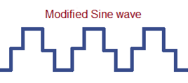
In the previous tutorial, a half wave bridge circuit with IR-2110 gate driver circuit was designed. The working principle of a modified sine wave inverter has been already discussed. Now it’s time to complete the circuit of Modified Sine Wave Inverter. The complete sine wave inverter can be designed using full bridge circuit and a step up transformer.The aim of this project is design an inverter which can output a quasi sine waveform having a frequency of 50 Hz and 220 V peak voltage. So all the building blocks will be combined in this tutorial to make the final circuit of the sine wave inverter.
Testing MOSFET – (Part 16/17)
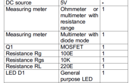
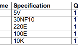
MOSFET are more commonly used transistors. They are known for their high switching speed and high input impedance. That is why they are preferred to be used in the fabrication of integrated circuits and the high frequency application chips. Individual MOSFET are also widely used in lots of applications. Before using a MOSFET in a circuit, it is important to check if it is not faulty. In a defective MOSFET, the drain may get shorted to the gate. This can cause the drain voltage feedback to the gate terminal and this voltage then feed to the driver circuit through the gate resistor which can blow the driver circuit further. Therefore it is better to test the MOSFET before using it in the circuit. As N-channel MOSFET are more common so testing of N-channel MOSFET is only discussed in this tutorial.
Driving High Side MOSFET using Bootstrap Circuitry – (Part 17/17)
When using MOSFET as a switch, it can be connected in two switching modes – high side switch and low side switch. Contrary to low side, the high side configuration of MOSFET requires some external circuitry to turn it ON. There are various methods for driving the high side MOSFET. The following three methods are most commonly used to drive a MOSFET as high side switch – 1. Dual power supply method2. Gate Driver IC method 3. Bootstrap circuitry method
Adjustable 0 to 30V 2A DC Power Supply Circuit (Part 1/13)

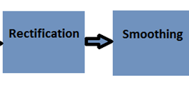
The power supplies are the mainstay of electronic circuits. The power supply circuits can be designed in many ways. There can be adjustable power supplies or can be fixed voltage power supplies. A power supply circuit is rated by the voltage or range of voltage it supplies and the maximum current it allows to draw by a load. Secondly, the households are provided with AC voltages as main supplies. A lot of electrical appliances like fans, fluorescent tubes, and others are capable of using AC voltages directly but most of the electronic devices require conversion of AC voltage to DC voltages for their operation. Any external power supply circuit needs to convert AC voltage to DC voltage for use by the electronic devices. In this project, an adjustable power supply circuit is designed which inputs AC mains and provides 0 to 30V 2A DC Voltage as output.
Adjustable +/- 1.25V to +/-22V 1A Power Supply Circuit (Part 2/13)
In the previous project, an adjustable power supply circuit having an output voltage in the range between 0V and 30V with the maximum current capacity of 2A was designed. A lot of times required DC supply should have both positive and negative voltages. In the previous project, the negative voltage could be provided to a device only by reversing the terminal connections manually. The circuit will input 220V-230V AC and generates a variable DC voltage in the range of +/- 1.25 V to +/-22V at the output. This power supply can provide a maximum current of 1A at the output. For making an adjustable power supply that would have both negative and positive voltages, a center tape transformer needs to be employed in the circuit design.
Adjustable 0 to 15V 1A Mini Power Supply (Part 3/13)
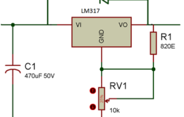
This project aims to build an adjustable 0 to 15V 1A power supply circuit. The circuit will work as a portable mini power supply for most of the electronic gadgets. The circuit could be used as power adaptor for smartphones, wearables, and computer gadgets. In this project, an adjustable regulated symmetrical positive power supply is designed.For reducing any fluctuation and ripples at the output the supply needs to be regulated so that it can provide a constant voltage at the output. Again like previous projects, the voltage is adjusted using a variable resistor. This power supply provides regulated as well as the adjustable voltage at the output.
Constant 12V Power Supply for LED Circuits (Part 4/13)

In the previous projects, adjustable power supply circuits were designed. Sometimes, the voltage to drive a specific circuit is already known and power supply circuit to output a constant voltage needs to be designed. In this project, a constant 12V power supply circuit is designed with an aim to power LED circuits.The circuit needs to be designed in a way that it should be void of any fluctuations or ripples. The circuit will input supply from main AC supplies and will convert it to a ripple free 12V DC supply. The circuit will be able to draw a maximum current of 1A.
Constant +/-9V DC Symmetrical Power Supply Circuit (Part 5/13)

In the previous project, a constant 12V DC power circuit with current limitation of 1A was designed. In this project, a symmetrical dual power supply with constant voltage outputs will be designed. A symmetrical dual power supply can provide two symmetrical voltages at the output with opposite polarity with respect to a common ground reference.Every electronic circuit needs a proper power supply at the input for its optimum functioning. The power supply of any device or circuit should be chosen as per its power requirements. In this project, a regulated power supply circuit which can output constant voltages of 9V and -9V with 1A maximum current is designed.
Making a Circuit Breaker (Part 6/13)
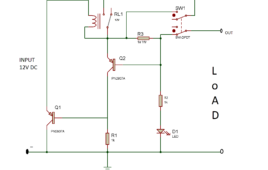
Protecting circuits from over current is an important aspect of circuit designing. The cause for over current can be intolerable voltage fluctuation in the power supply, short circuiting, failure of a device or component and overloading. Usually, for the protection of circuits from over current and so the damage from overheating of components, electronic fuses are used in their power supply sections. Electronic fuses are thin metallic wires which melt down over the passage of a threshold current. In the design of power circuits, apart from electronic fuses, circuit breakers are also used for circuit protection. Any circuit breaker operates like a relay which has the ability to detect a threshold current level and disconnect the rest of the circuit by tripping off the supplies.
Audio Filters: The working and classification of microphones – Part 3
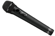
In the previous tutorials, physical properties of sound waves and acoustic waves were discussed. Sound or Acoustic Waves are in the form of vibration. Sound needs to be converted into electrical signals so that it can be processed by electronic circuits. So, the sound which is a mechanical energy must convert into electrical energy and must be precisely represented as an electrical waveform (analog) for any signal processing operations. So, there is need of a device which could sense the audio signals efficiently and convert them into electrical signals.
Audio Filters: The working and classification of speakers – Part 4

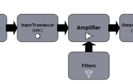
In the previous tutorial, working principle and classification of microphones was discussed. The microphone is an input transducer which converts sound waves into electrical signals. The audio signals from a MIC are amplified by a preamplifier and transferred to the main audio unit. The audio unit might comprise of amplifier and/or filter circuit or may have other circuitry to store audio to a computer. The amplified or stored audio is reproduced using another type of transducer which is called speaker. The Speaker is a type of output transducer which converts the electrical signal into audio signal. Speakers are enclosed in a rectangular or square shape cabinet. The shape of the box affects the quality of the sound. The cabinet consists of different types of transducers/speakers which produce different types of audio frequency. Each transducer is called as ‘driver’ and the whole cabinet is known as ‘loudspeaker’.
Audio Filters: Understanding the filters – Part 5
In the previous tutorials, two of the most important building blocks of an audio system – Microphone and Speaker were discussed. An audio system is designed to receive audio signals (via microphone), record audio in some storage, transmit audio (through wired or wireless communication channels) and reproduce audio signals (via speakers).
Audio Filters: Designing a two-way audio crossover – Part 6
In the previous tutorial, fundamentals of audio filters were discussed. The audio filters can be passive or active depending upon the use of passive or active components in their designing. On the basis of frequency response, filters can be classified as high pass, low pass, band pass, Notch, band reject, T-Notch, all pass and equalizer filters. In this tutorial, an audio crossover will be designed. The Audio crossover is an electronics circuit which splits the audio signal into two or more frequency bands. These frequency bands are then, sent to the different audio drivers (Twitters, Mid Range and Woofers). A single speaker is not capable to serve the whole range of audible frequencies due to the limitations of its construction. So, different drivers (speakers) are required to deliver different range of audio frequencies.
Audio Filters: Designing an audio equalizer – Part 7
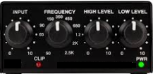
In the previous tutorial, an audio crossover was designed using high pass and low pass audio filter. In this tutorial, an audio equalizer will be designed. An Equalizer (abbreviated as EQ) is an audio equipment which cut or boosts the certain frequency components from the audio signal. This process of adjusting the frequency components is called as Equalization.The equalizers are widely used in the audio systems during recording of sound as well as in amplifiers and mixers. As they are used in the audio system so are called Audio Equalizer.
Audio Filters: Designing an audio mixer – Part 8
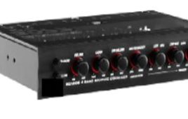
In the previous tutorial, an audio equalizer was designed. In this tutorial, now an audio mixer will be designed. The Audio Mixer is an electronic device which combines and modifies the audio signals. The audio signals can be either in digital form or analog form. In digital form, the analog audio signals are encoded so that the audio information in the signal becomes independent of the amplitude of the signal. Both analog and digital signals can be combined by different types of audio mixers. For mixing digital audio signals, digital signal processing techniques are used while for combining the analog audio signals, generally operational amplifiers are used.
Designing 12V Lead-Acid Battery Constant Voltage Limited Current Charger for UPS (Part- 2/17)
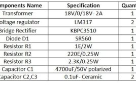
In this tutorial, a constant voltage charger for the 12V lead acid battery will be designed. The lead-acid batteries can be charged in different ways or modes. In this tutorial, a constant voltage charger will be designed for charging the lead-acid battery. The battery is required to be supplied limited current which saturates once the peak terminal voltage is achieved in the charging process. Depending on the per cell voltage of the 12V battery, the maximum rated voltage of the battery varies from 13.5 V to 14.6 V. In this tutorial, the charger circuit is designed for charging a lead acid battery having peak terminal voltage of 14.4 V.
Basics of Li-ion Battery Charging (Part- 3/17)
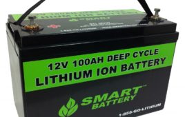
Lithium-ion batteries are another popular type of batteries that are used in the Uninterruptible Power Supply (UPS) designs. These batteries are commonly used in portable electronic devices. These are low maintenance batteries having high energy density, small size and light weight which makes them suitable for use in most of the portable devices. But, due to high energy density in comparison to the weight and volume of the Li-ion Battery, there are also some safety concerns while charging the Li-ion batteries. Before designing a charger circuit for these batteries, let us first understand charging methods and topologies involved in charging Li-ion batteries. Also, precautions required in handling, storing and disposing of these batteries are must to know.
Designing constant current and constant voltage source for single cell Li-ion battery charger (Part- 4/17)
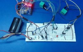
In the previous tutorial, the basics of Lithium ion batteries were discussed. Also, it was discussed how it is important to handle these batteries with care. as mentioned in the previous tutorial, that Lithium ion batteries need to be charged using CC-CV method, in this tutorial, a Li-ion battery charger for a single-cell Li-ion battery of nominal voltage 3.7 V will be designed. There are charger modules available in the market which can be used to charge the Li-ion batteries. In this tutorial, a charger built using the basic electronic components including Linear Regulator will be designed from scratch. The charger circuit will be customized as per the battery specifications and the charging requirements.