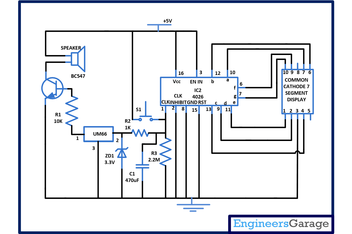
Different kinds of doorbell are available in market which produces different sounds but the important feature of our circuit is it not only produce musical sound but also indicate the number of times door bell is pressed. In our circuit it will display the counting from 0 to 9. You can also increase the number of person it can count with little modification in circuit. You do not require to press the reset button when counting reaches to 9 as it automatically starts its counting again from 0 when 9 is reached. You can also vary the time for which door bell sound.
This electronic doorbell circuit is based on 4026 IC which is a Johnson counter IC commonly used in digital display. It can be used in various applications like in 7 segments decimal display circuit, in clocks, timer etc. Advantage of 4026 counter-
1. It contains counter and 7 segment decoding in one package.
2. It can be easily interface with 7 segment types.
3. Ideal for low power display.
4. Operated at wide range of temperature from 5V to 20V.
5. The big advantage of the 4026 counter IC is that it can drive a 7-segment display without needing a decoder driver IC
For producing melodious sound IC UM66 is used. Do not provide voltage more than 3.5 V to UM66 IC because excess voltage may destroy this IC. So care should be taken while using this IC. That’s why we have used a zener diode at the supply input pin of UM66.
Working of electronic doorbell circuit–
Assemble the circuit properly. Connect the pin 3 of IC 1 to supply and on the display. If pin 3 is connected to ground we will get a blank display on 7 segment output. Also connect the pin 15 which is a reset pin to ground so that when counting reaches to 9 it will reset the counter to zero automatically when switch is pressed. Also connect the pin 2 that is disable clock (clk inhibit) pin to ground. As 4026 counter advances one by one by receiving positive pulse, for this clock inhibit pin should be grounded. If it is connected to supply than counter advancement will be inhibited means there will be no meaning of clock pulse.
Now apply power supply. Whenever a visitor arrives in home he or she will press the door bell switch (S1). Initially zero will be displayed on the 7 segment display. As soon as first visitor presses the switch S1 it will provide a clock pulse to pin 1 (which is a clock input pin) of IC1. After receiving the clock pulse, 4026 IC counter advances and 1 will be displayed on common cathode of 7 segment displays.
When second visitor enters, same phenomenon occurs till count reaches 9. When it reaches 9 one cycle is completed and counter starts from zero.
Circuit Diagrams
Project Components
Project Video
Filed Under: Electronic Projects
Filed Under: Electronic Projects


Questions related to this article?
👉Ask and discuss on EDAboard.com and Electro-Tech-Online.com forums.
Tell Us What You Think!!
You must be logged in to post a comment.