Floods are generally considered natural disasters. Depending on their severity, they can have a devastating impact on human life, agriculture, and infrastructure. In serious cases, floods can result in significant economic losses due to property damage, disruption of transportation, and the cost of emergency response and recovery efforts.
This is why, flood monitoring is crucial for public safety, infrastructure protection, economic stability, and quick and effective disaster responses. With the increasing frequency and intensity of extreme weather events linked to climate change, monitoring has become even more critical.
In this project, we’ll design an Internet-of-Things (IoT) based online flood monitor using the ThingSpeak platform — a popular IoT analytics service platform. We’ll build this device on an ESP8266 WiFi development board, integrating it with the ThingSpeak server for the online flood indicator.
Required components
- ESP8266 x1
- Red LED x1
- Green LED x1
- HC-SR04 Ultrasonic sensor x1
- 330Ω Resistor x2
- Connecting wires or jumper wires
Circuit connections
This flood-monitoring device uses the ESP8266 Wi-Fi development board to measure the level of water in a river, lake, or any water body. If the water level rises to an alarming level, the device turns on the flood indication.
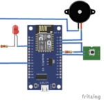
ESP8266 is interfaced with the HC-SR04 ultrasonic sensor. The sensor’s echo and trigger pins are connected to ESP8266’s GPIO2 and GPIO1 pins, respectively. The sensor’s VCC and GND pins are connected to ESP8266’s 3V out and ground pins.
Two LEDs are also interfaced with ESP8266 for on-spot indication. A red LED is connected to ESP8266’s GPIO3 and a green LED is connected to ESP8266’s GPIO4 via series resistors (330 ohms). The LEDs are connected with ESP8266 to source current from its pins.
Creating a channel on ThingSpeak
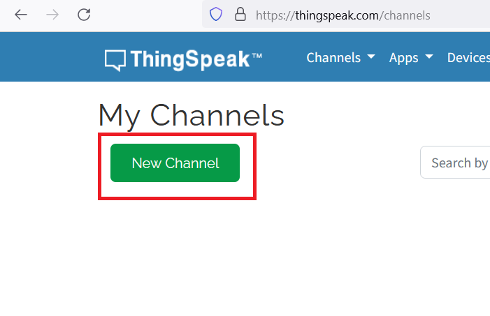
After the circuit connections of the device are complete, we must create a ThingSpeak channel for it. Visit ThingSpeak.com and sign up for an account. Verify your email and login to your ThingsSpeak account. Click on ‘Create New Channel’ to create a channel.
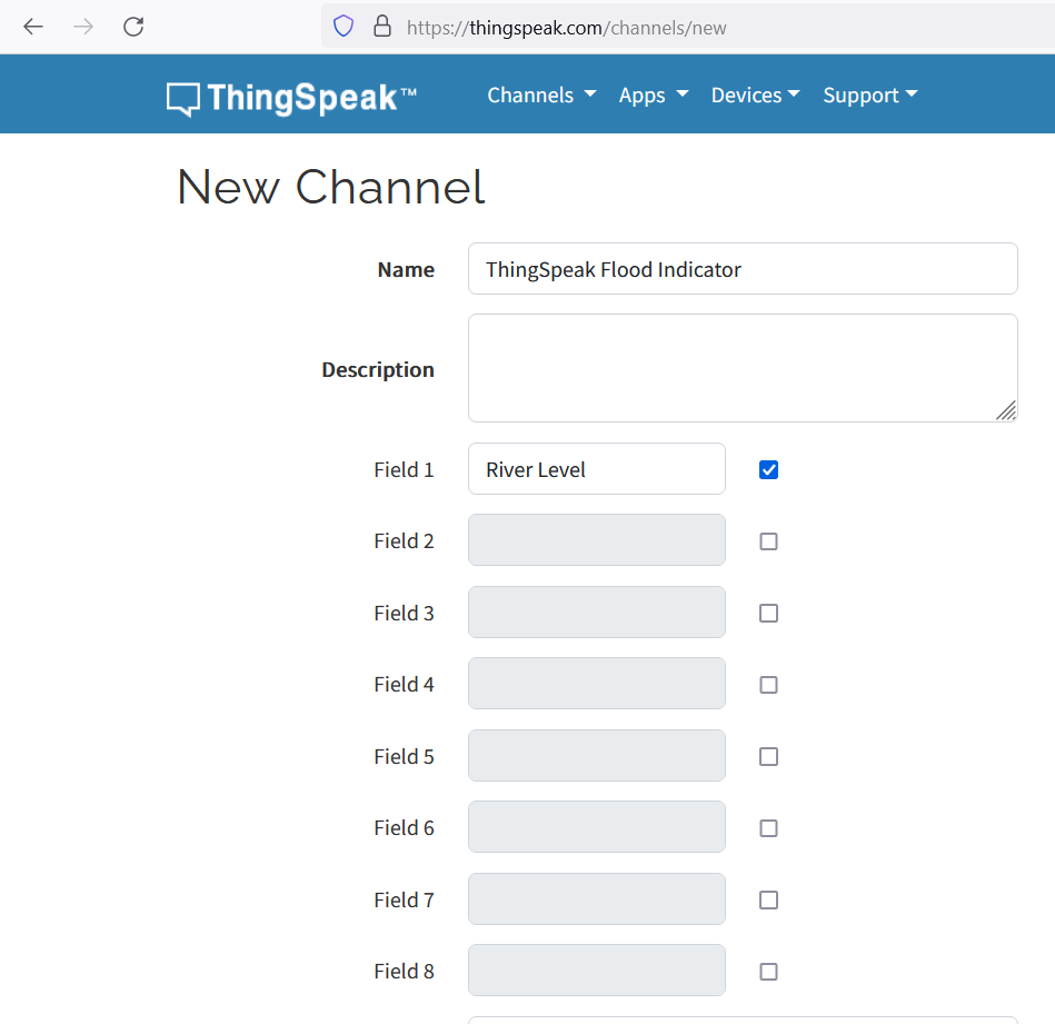
Name the channel, ‘ThingSpeak Flood Indicator’. Then, rename the field1 to ‘River Level’ and click on ‘Save Channel.’
In the ‘Private View’ tab, click on the ‘Add Widgets’ button.
Select ‘Lamp Indicator’ and set its attributes as shown below.
Click on ‘Create’ button to finish creating the widget. Now, you have a channel on the ThingSpeak server that can monitor water levels and warn of a potential flood.
Note down your channel ID and Author key from the main dashboard, as well as the Write API key from under the ‘API Keys’ tab.
These will be required later in the sketch.
The Arduino sketch
Upload the following sketch to ESP8266. Remember to replace the ThingSpeak channel ID, Author Key, Write API Key, Wi-Fi SSID, and Wi-Fi password with your own.
How it works
The ultrasonic sensor is interfaced with ESP8266, which measures the water level. If the distance measured between the sensor and the (lake or river) water level is less than four meters, it signals a flood.
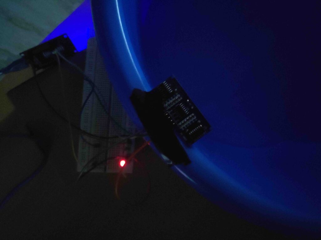
If ESP8266 measures a water level above four meters, a green LED remains ON. If ESP8266 measures a water level below four meters, a red LED is switched ON and the green LED is turned OFF.
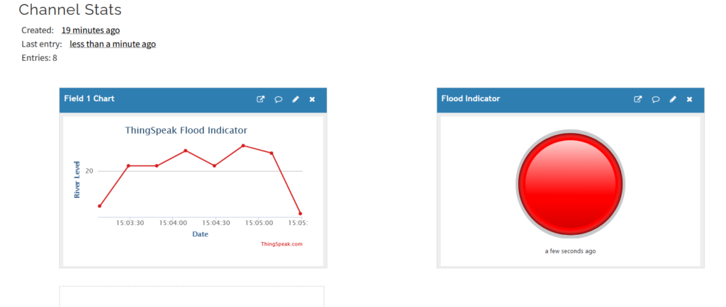
The value of the distance between the sensor and the water level is sent to the ThingSpeak server at regular intervals. The value of the river level for the ThingSpeak server is under field1. If this value goes below four, the ThingSpeak’s lamp indicator also turns red.
The code
The sketch begins by importing the ThingSpeak.h and ESP8266WiFi.h libraries. The ThingSpeak.h library is required to connect and communicate data with the ThingSpeak server. The ESP8266WiFi.h library is used to connect ESP8266 with a Wi-Fi network.
The variables are declared for the pin assignments for the ESP8266, the HC-SR04 ultrasonic sensor, and the LEDs. This is followed by declaring the variables to store the ThingSpeak channel ID, Write API key, Author Key, Wi-Fi SSID, and Wi-Fi password. The variables are declared and stored in milliseconds, current milliseconds, period (equal to 10000 milliseconds), duration, and distance. A Wi-Fi client is instantiated.
In the setup() function, the pins connected to the sensor’s trigger pin and the LEDs are configured for a digital output. The ESP pin connected to the sensor’s echo pin is configured as a digital input. The LEDs are turned OFF by passing a LOW signal. The baud rate for the serial console is set to 9600 bps.
The Wi-Fi client is initialized and connected to your Wi-Fi network. The Wi-Fi client initializes an object with the ThingSpeak server. The current time lapsed is stored as a ‘startmillis’ variable.
In the loop() function, ESP8266 transmits a LOW-to-HIGH pulse to the sensor’s trigger pin, reading the distance between the sensor and the water level by calling the pulseIn() method. This method returns the duration of the ultrasonic signal. The distance is calculated in the ‘distance’ variable using the following equation.
Distance= (Time x Speed of Sound in Air (340 m/s))/2
If the distance measured is less than four meters, a red LED is turned ON and a green LED is turned OFF. Otherwise, the red LED remains OFF and the green LED remains ON. The current time is stored as a ‘currentmillis’ variable. It’s deducted from the value in the ‘startmillis’ variable to determine the time that elapses between sensor readings.
If the time elapsed is greater than 10000 milliseconds, the distance value is updated to the ThingSpeak server by calling the ThingSpeak.setField() and the ThingSpeak.writeFields() methods. The current time is reset to the start time.
Results
You may also like:
Filed Under: Electronic Projects, ESP8266.







Questions related to this article?
👉Ask and discuss on EDAboard.com and Electro-Tech-Online.com forums.
Tell Us What You Think!!
You must be logged in to post a comment.