Here is a simple project on how to control fan or dc motor speed with microchip pic16f877 microcontroller. There are numerous ways to control the speed of motor(or fan). Varying current, voltage and resistance etc. But when it comes to controlling the speed using microcontrollers. Then the PWM (Pulse width modulation) technique is most effective one. Pulse width modulation reduces the direct current/voltage pulse duration, which ultimately reduces the output current and voltage at output. In pulse width modulation the digital signal high and low time period is varied to output a desired voltage. Varying the dc voltage in pulses is know as duty cycle. A typical pulse width modulation diagram is show below with different duty cycles.
|
Varying duty cycle signals are shown in the pic on the right side. High pulse is generally termed as duty cycle. Original signal high pulse is 65% and low 35%. Thus original signal duty cycle is 65%. The work is only done in duty cycle period. Varying duty cycle signals are shown below the original. Duty cycle of easy signal is different then others. 70%, 30% and 90% respectively.
|
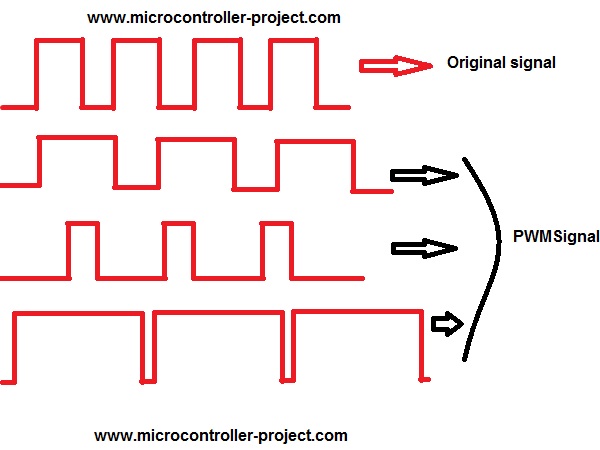
PWM(Pulse width Modulation) waves
|
Pic microcontroller speed control project requirements
- Pic16f877 microcontroller
- L293d h-bridge Motor driver Ic
- DC Motor or small fan
- Crystal 20MHz
- Push Buttons
- connecting wires
- Bread board or PCB
- Power Supply battery
Their are two pins dedicated for generating pwm output in pic16f877 microcontroller. These two pins are of port-c pin#1 and 2. They are named as CCP1 and CCP2 (CCP stands for Capture,compare and PWM). These two pins can be used in capture, compare and Pwm mode.They can also be used as digital I/O. We first have to configure them whether we want to use them in CCP mode or as digital I/O (input/output). We have to configure some registers to achieve this.
Registers associated with CCP1 & CCP2 Module.
Registers associated with CCP1 & CCP2 Module.
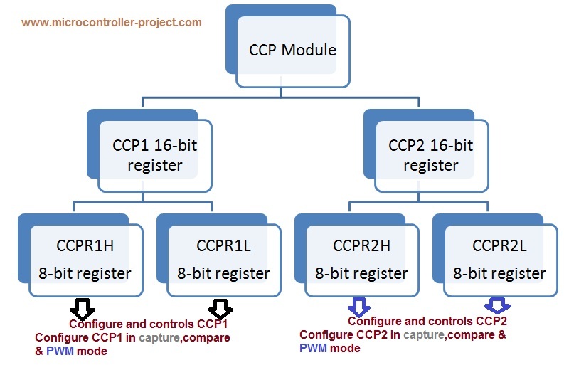
PIC16f877 CCP module Hirerachy
To Control and configure CCP1, CCP1 register is used. CCP1 is a 16-bit register which is further divided in to two 8-bit registers CCPR1H(Capture,compare,PWM register 1 high byte) and CCPR1L(Capture,compare,PWM register 1 LOW byte).These two registers are controlled by CCP1CON(Capture,compare,PWM 1 control) register. Alternatively CCP2CON is used to control the CCP2 module.

CCP1CON and CCP2CON register bits
The PWM signal generated by PIC 16f877 provides 10-bit resolution. Which means it can calculate up to 2^10 = 1024. The 10 bit value is loaded in CCPR1L and CCP1CON<5:4> registers. Now Set the Period and duty cycle for the signal. The period is set in PR2 register. PR2 is an 8-bit register. Timer 2 runs from 0 upto the value loaded in PR2 register. Upon reaching the value it starts again from 0. When all the values are loaded in the registers then run the timer to generate the Pwm. Dont forget to set the timer prescaler. I set it to 4.
Note: Only Timer 2 can be used for PWM generation in Pic16f877.
Note: Only Timer 2 can be used for PWM generation in Pic16f877.
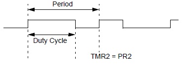
Period and duty cycle wave forms
To drive a dc motor or fan through the generated pwm wave you need to build a motor driver circuit. Microcontroller output voltage is very low and it can not drive huge loads like dc motors and fan etc. Make an H-Bridge circuit to drive motor or simply use L293d ic to drive the motor. L293d is a motor driver ic which can drive heavy loads. Full description of the ic with pin out is given in this tutorial (L293d pin out and working).
The circuit diagram of the project is given below. Six Push buttons are attached with port A of the pic16f877 microcontroller. These push buttons are used to change the speed of the motor. Their are six speed levels press these push buttons to change the speed of fan or motor. CCP1 pin is attached to L293d pin no 10. The motor rotates in anti clock wise direction when power is turn on. You can drive the motor in clock wise direction, just connect CCP1 with pin 15 of L293d and make pin 10 ground. 20 Mhz crystal is used in the project. Using a crystal of low frequency can also effect the motor speed.
The circuit diagram of the project is given below. Six Push buttons are attached with port A of the pic16f877 microcontroller. These push buttons are used to change the speed of the motor. Their are six speed levels press these push buttons to change the speed of fan or motor. CCP1 pin is attached to L293d pin no 10. The motor rotates in anti clock wise direction when power is turn on. You can drive the motor in clock wise direction, just connect CCP1 with pin 15 of L293d and make pin 10 ground. 20 Mhz crystal is used in the project. Using a crystal of low frequency can also effect the motor speed.
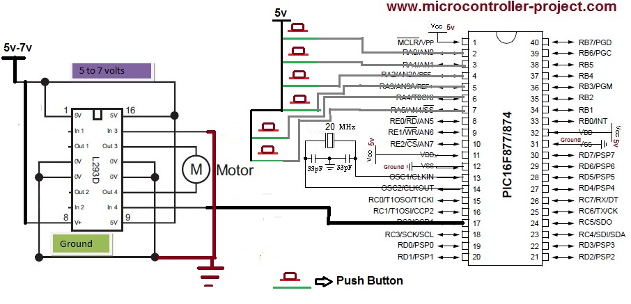
Speed control of DC motor with Pic 16f877 microcontroller and l293d motor driver ic – Circuit Diagram
The code part is simple. It is written in c language using Mplab and HTC(high tech c compiler). First include the header file htc.h. This header file is necessary to be included if you are using htc compiler. Then the crystal frequency is defined which is 20 Mhz. Then individual pins are defined for each button. In the main function ADCON1=0x06 instruction initializes all pins of port A as digital. This instruction is very important. Port A of pic16f877 is multiplexed. It can be used as digital I/O as well as Analog input pins. ADCON1 register is used to configure port A to be used as ADC or digital I/O. Loading 0x06 in ADCON1 makes port A all pins as digital I/O. Now after initializing port A pins as digital I/O you need to initialize them as digital input or output. TRISA register is used to initialize them as digital input or output. Loading TRISA=0b11111 will initialize all pins as digital input. TRISC2 register is initializing port c pin 2(CCP1) as output.PR2 register is used to set timer 2 period. I loaded 0xFF in it, which means timer increments uptill 255 and then back starts from 0.
In rundutycycle() function pwm signal in generated. The function of each instruction is given with it. The status of switches s1 to s6 are also checked in this function and duty cycle is varied according to the switches status. T2CON is timer 2 control register. To set its bit functions please refer to the data sheet of pic 16f877 microcontroller.
Download the project code, hex file(code) and simulation. Folder includes all the project files. The code is compiled using htc(high tech c compiler) and mplab . Simulation is made in proteaus 8.0.Please give us your feed back on the project.
Filed Under: Microcontroller Projects, PIC Microcontroller.

Questions related to this article?
👉Ask and discuss on Electro-Tech-Online.com and EDAboard.com forums.
Tell Us What You Think!!
You must be logged in to post a comment.