This tutorial is about how to measure dc direct current with arduino. I am going to measure current using a hall effect sensor by allegro ‘Acs712′. Acs712 has three variations. ACS712ELCTR-05B-T can measure current from -5 to +5 Amperes. ACS712ELCTR-20A-T can measure current from -20 to +20 Amperes. ACS712ELCTR-30A-T can measure current from -50 to +50 Amperes. It can measure Ac current as well as Dc. For this tutorial i am only going to measure dc current. I am interfacing ACS712ELCTR-05B-T -5 to +5 amps sensor with arduino. The measured value is then displayed on a 16×2 lcd. I am using arduino lcd shield to avoid messy circuit and easy to handle circuit. Arduino lcd shield is interfaced in 4-bit mode with arduino.
In the previous tutorial we learned how acs712 current sensor works. Its pin out and pins definition/working. We derived formula for all the three types of acs712 current sensors. In this tutorial we are using the formula derived previously. We also wrote some dummy codes for testing. I recommend you to please take the previous tutorial. You can easily understand the code written below if you take the tutorial.
In the previous tutorial we learned how acs712 current sensor works. Its pin out and pins definition/working. We derived formula for all the three types of acs712 current sensors. In this tutorial we are using the formula derived previously. We also wrote some dummy codes for testing. I recommend you to please take the previous tutorial. You can easily understand the code written below if you take the tutorial.
|
Arduino lcd shield is placed on the top of arduino uno. Since the shield is made for residing on the arduino uno. Analog channel A5 of arduino is used to measure the voltage output by the acs712 current sensor. The corresponding voltage is then converted to current value using the formula that was discussed in the previous tutorial. Acs712 current sensor is supplied power by arduino uno +5 volt output. Arduino ground is directly connected to acs712 ground.
|
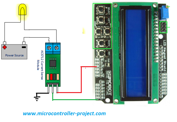
Acs712 current sensor measuring current using arduino.
|
I am using a power supply(30 volt, 10 Amperes) for supplying current to a dummy load. I increase the input voltage and the current output also increases. I connected the acs712 current pins in series to the load. Always connect the acs712 in series to a system whose current is going to be measured. Recall the high school lectures “Current is only measured in series”. Never connect the sensor in parallel to load, other wise the sensor will burn in a second if the current is high.
The code is simple first i included the “LiquidCrystal” library of arduino. This library is used to control the arduino lcd shield. Than the pins occupied by the arduino lcd shield on arduino uno are defined and a reference to library is made with the name ‘lcd’. Now each library function is called with this reference ‘lcd’. In the setup function the arduino lcd shield is initialized and an introduction message is displayed on the first line of the lcd. The message is “ACS712-5B Test”. The shield character displaying dimension 16×2, meaning it has 16 coulombs and 2 rows. Rows start from 0 to 1 and coulombs start from 0 to 15.
The readvcc() function is arduino secret voltmeter it measures the internal voltage on which the arduino is working. The function is composed of in line assembly commands and is not easy to understand. For this tutorial only consider it as a function measuring the arduino operating voltage. We need this function to identify the voltage that we are supplying to acs712 sensor. Remember that we are operating our acs712 with power from arduino. Now we know about the voltage on which the acs712 is operating its easy to calculate the acs712 reference voltage. Just divide the operating voltage by 2. The statement vcc/2 is doing the same this in the code.
Then i am taking 150 analog voltage samples and then averaging them to obtain a precise value of voltage output by the acs712 current sensor. Now we have all the values with us. We put them in to the formula and the current is calculated. The final current value is displayed on the 2 line of the arduino lcd.
|
I performed the test and results are listed on the right side. My power supply is not very good. Its only up to 1.5 amperes. At low currents the sensor performs perfect. But at high current the sensor output is little low than original. It may be due to my power supply its not very efficient.
|

Acs712 current sensing results
|
Filed Under: Arduino, Microcontroller Projects

Questions related to this article?
👉Ask and discuss on EDAboard.com and Electro-Tech-Online.com forums.
Tell Us What You Think!!
You must be logged in to post a comment.