Fasted Finger First is an important circuit which is commonly used in quizzes, games and other multi-player activities. In quiz events, the circuit is generally used in rapid fire rounds where it has to be determined that which participant has first responded to the question. It is necessary to use such circuit in a quiz as many times, there is a minor difference between the responses of participants. In such cases, it becomes difficult by a human observer to determine which participant has responded first to the query.
In this project, a simple electronic circuit for fastest finger first has been designed. The circuit is based on JK Flip-Flops. The Flip-flop is a digital electronic circuit with two stable states that can be used to store binary data (0 or 1). The JK Flip-Flop is used here as it is the most versatile flip-flop. For JK Flip-Flop, 7473 IC is used in this project. The 7473 IC is a dual J-K flip flop IC.
This circuit has been designed for four-player quiz. Each player has a button which has to be pressed for response. There are seven segment displays interfaced in the circuit as such that there is a seven segment display for each player. Each player is assigned a number. The seven segment corresponding to the player who responded first displays the assigned number on response. At the same time, an LED glows to indicate the response.
The circuit is also capable to determine a tie between two or more players. If two or more players would have pressed the respective buttons at the same time, the seven segments corresponding to them will display their numbers simultaneously. A buzzer is connected in the circuit which makes little beep sound when any switch is pressed. The circuit can be reset by a reset switch for next round. The circuit can be extended to more players by interfacing additional buttons, 7473 ICs and seven segment displays.
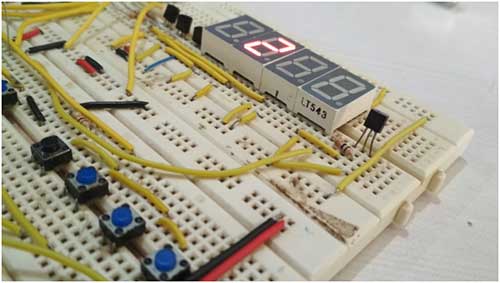
Fig. 1: Prototype of 7473 JK Flip Flop IC and 555 IC based Fastest Finger First Circuit
Component Required:-

Block Diagram –
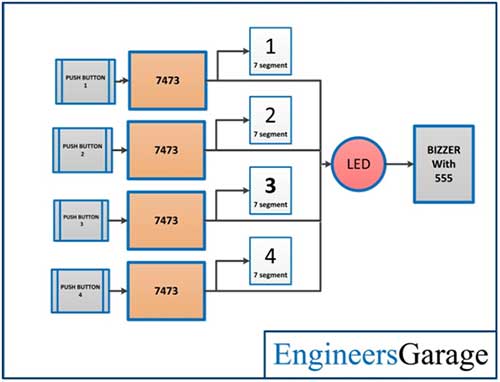
Fig. 2: Block Diagram of 7473 JK Flip Flop IC and 555 IC based Fastest Finger First Circuit
Circuit Diagram –
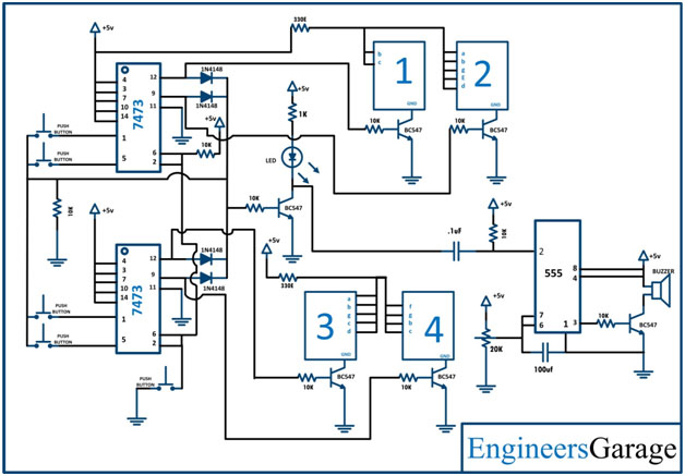
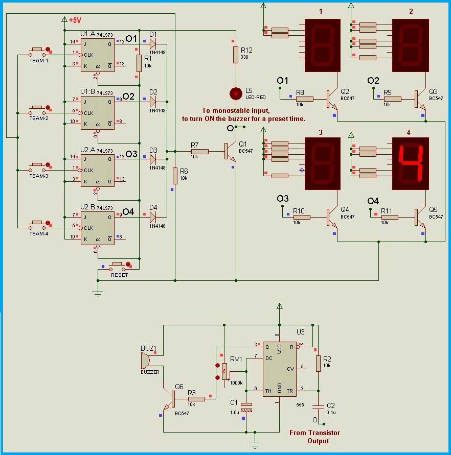
Fig. 3: Circuit Diagram of 7473 JK Flip Flop IC and 555 IC based Fastest Finger First Circuit
Circuit Connections –
This Fastest Finger First circuit is a simple electronic circuit based on 7473 IC and 555 timer IC. This circuit has been designed by connecting the following components as follow-
Push Buttons – There are four push buttons connected in the circuit, one for each player. The push buttons are most suitable for use in quizzes.
7473 Dual JK Flip Flop ICs – There are two 7473 ICs used in the circuit. Each 7473 IC has two JK Flip-Flops. So, two ICs are enough for four players. The DIP package of the IC is used as the circuit is designed and tested on a breadboard. The typical operating voltage of the IC is 5V. The 7473 is a 14-pin IC. It has the following pin diagram –
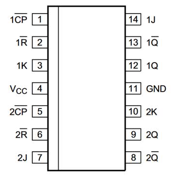
Fig. 4: Pin Diagram of 7473 Dual JK Flip-Flip IC
The IC has the following functional diagram –
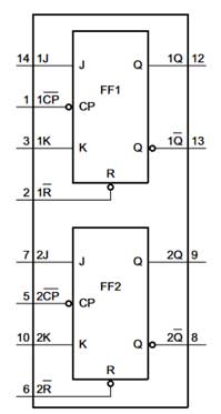
Fig. 5: Functional Diagram of 7473 Dual JK Flip-Flip IC
One terminal of the push buttons is connected to pin 1 (1CP) and 5 (2CP) of the IC. These pins are internally connected to Clock pins of the JK flip-flops. The other terminal of the push buttons is connected to the pin 9 (1Q) and 12 (2Q) of the IC. These pins are the output pins of the JK Flip-Flops. The output pins of the JK Flip-Flops are connected to the terminal of the push buttons through diodes. Each push button is connected between clock of one JK flip-flop and output of the all the JK Flip-Flops. The pins 14 (1J), 3 (1K), 7 (2J) and 10 (2K) are connected to 5V DC. The Reset button is connected to pins 6 (1R) and 2(2R) of the IC. The pins 6 and 2 are the Clear pins of JK Flip-Flops. The pin 4 (VCC) of the IC is connected to 5V DC and pin 11 (Ground) of the IC is connected to common ground. The output pin of each JK Flip-Flop is also connected to base of a switching transistor BC547. The output of the diodes, connected at the output pins of the JK Flip-Flops, is also connected to the base of a switching transistor BC547 which in turn is further connected to LED and 555 IC. For increasing the number of participants, additional 7473 ICs can be connected in the circuit.
BC547 Transistors – BC547 is an NPN bi-polar junction transistor. A transistor, stands for transfer of resistance, is commonly used to amplify current. A small current at its base controls a larger current at the collector and emitter terminals. There are six BC547 transistors used in the circuit. The four of these are used to sort the output of the JK Flip-Flops where the output of the JK Flip-Flops is connected to the base of BC547 transistors via series resistances of 10K ohms. The collector terminal of these diodes is connected to ground pin of the common cathode seven segments. One transistor is used to sort the output of diodes where the base of it is connected to output of all the diodes. The collector terminal of this transistor is connected to LED and pin 2 of the 555 IC. One transistor is used to drive buzzer connected at pin 3 of the 555 IC. The emitter terminal of all the transistors is connected to ground.
7-Segment Displays – There are two types of seven segment displays – common cathode and common anode. In this circuit, common cathode seven-segment displays are used. The cathode terminal common to all LEDs in the seven segments is connected with the collector of the BC547 transistor. The anode terminal of the seven segments is connected to 5V DC via series resistance of 330 ohms. The seven segments are driven by the output of the JK Flip-Flops. In the circuit, seven segments are numbered 1 to 4 which is indication of the number displayed by that seven segment. The anode pins b and C of seven segment 1 is connected to 5V DC to display number 1 on it. Similarly, anode pins a, b, d, e, and g of seven segment 2, anode pins a, b, c, d and g of seven segment 3 and anode pins f, g, b and c of seven segment 4 are connected to 5V DC to display numbers 2, 3 and 4 respectively.
LED – An LED is connected at the output of the diodes via a switching transistor BC547. This LED is used to indicate reception of response. The LED is turned off when the JK Flip Flops are reset. The anode terminal of this LED is connected to 5V DC while cathode terminal is connected to collector pin of the transistor.
555 Timer IC – The 555 IC is used in the circuit to drive the buzzer. The IC is used in monostable mode to drive the buzzer for a short period of time. In monostable mode, the output of the IC remains in the low state until there is a trigger input (at pin 2 of the IC). For operating 555 IC in monostable mode, the input from the collector pin of the transistor is given at pin 2 of the 555 IC via a capacitor of 0.1uF. The pin 2 of the IC is also connected to 5V DC through LED and a series resistor of 10K ohms. The pins 6 and 7 of the IC are shorted and connected to a potentiometer. A capacitor of 100 uF is connected between pin 6 and the ground. The pins 4 and 8 of the IC are connected to 5V DC and pin 1 is connected to common ground. The monostable pulse from 555 IC is drawn from pin 3 of the IC.
Buzzer – The buzzer beeps when a participant presses a switch after the reset. The buzzer is connected between the collector pin of respective transistor and 5V DC. The respective transistor has its base connected to pin 3 of the 555 IC via a resistor of 10K ohms.
Power Supply – The circuit operates on 5V DC. This voltage can be supplied through a suitable battery connected to the circuit through 7805 voltage regulator IC.
The physical installment of this circuit is also important. This circuit has been designed for any event involving up to four participants. The main circuit must be placed near the event manager or the person who asks the questions. This is because the RESET has to be done after each question.
The push buttons or any type of switches that are selected should be placed at the podiums of the participants or participating teams. From the main circuit, four wires should be laid to each podium. There will be need of two wires for the push button terminals and two wires for the light/LED indicator at the podium, where light/LED is optional. It should be taken care that suitable transistor or MOSFET must be used to drive the light bulb/LED. The buzzer can be connected near the main circuit through the transistor controlled by the diode output.
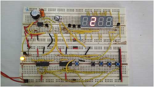
Fig. 6: Image of 7473 JK Flip Flop IC and 555 IC based Fastest Finger First Circuit
How Circuit Works –
The working of this circuit is based on a feedback technique applied to JK Flip-Flops. There is a feedback provided between outputs of the JK Flip-Flops and one terminal of the push buttons. The output of the Flip-Flops is connected to respective anode of diodes. All the diodes are shorted at their cathode terminals. The output of the shorted diodes is used as clock of the flip-flops at common node of the push buttons.
Initially, when no participant has pressed any switch, the output of the JK Flip-Flops stays LOW and so the output of the diodes also stays LOW. When any participant presses her push button, a LOW signal is supplied to the clock input of the respective JK Flip-Flop. This LOW input appears as a negative edge of a pulse. So, the output toggles from LOW to HIGH of the respective JK Flip-Flop.
As the feedback is provided using shorted diodes, even if one of the outputs is HIGH, the feedback signal also sets to logic HIGH. So, the common node of the push buttons is set to logic HIGH. Now, even if, another participant operates the push button, the clock input would remain HIGH but not a negative edge. So, only the output corresponding to the participant, which operated first, will stay HIGH.
Before going to the next event/question, the outputs of all the JK Flip-Flops must be LOW. For this purpose, a RESET button is connected with all the Flip Flops, which clears the outputs of all the Flip Flops. By clearing the outputs through RESET signal, the output of diodes are set to LOW i.e. the feedback signal is again revered to LOW. So, the circuit returns to the initial state.
The circuit operates even in the tie situations i.e. when more than one participant operates their respective buttons at the same instant. This is possible because of the feedback technique. As the required clock signal is LOW, the inputs are acceptable until the feedback is LOW. At this LOW situation, all the flip flop outputs can be turned HIGH by operating the push buttons at a time. But, if at least one of the outputs is HIGH, the feedback becomes HIGH and further inputs are not acceptable. This feature makes the circuit flawless.
The output of JK Flip-Flops is connected to seven-segment displays. The maximum output current that can be supplied by the flip flop output pins is around 10mA or even less depending on the exact part number. So, the seven segments cannot be connected directly to the output of the JK Flip-Flops. In order to amplify output current from JK Flip-Flops, either BJT (BC547, 2N2222 etc) or MOSFET (2N7000, 2N7002 etc) need to be used. A transistor (BJT or MOSFET) is also required as the same current is used to drive LED and as trigger input to 555 IC operating in monostable mode. The seven segments also must be connected in the circuit via a resistor of 330 ohms.
Here, four single digit 7-segment displays are connected such that each display shows a fixed number. The first 7-segment display is wired to show number 1, second 7-segment display is wired to show number 2 and so on. The respective display is enabled by using the output of its JK Flip-Flop.
In the circuit, an LED is connected at the output stage of shorted diodes using a transistor. A buzzer can also be used instead of LED. If a buzzer of voltage rating above 5V is to be connected in place of LED, then it must be connected through a 5V relay. In such case, the buzzer must be operated through relay. This buzzer or LED operates until RESET/Clear input is given to the JK Flip-Flops. So, a buzzer with short and fixed duration can be selected or a monostable circuit based on 555 timer IC can be used that makes a beep sound via buzzer when output of any flip flop goes HIGH. In cascaded circuits, only one buzzer is sufficient for entire circuit irrespective of number of circuits cascaded. In this circuit 555 IC in monostable mode is used to drive the buzzer. An LED is also connected such that it remains ON, after receiving a response.
The monostable circuit must turn ON the buzzer only for a fixed time period. The time period of the monostable circuit to turn ON the buzzer can be preset to desired value using the below formula –
T=1.1*R*C seconds
For example –
If R= 10K Ohms (10 000 Ohms) and C= 100 Micro Farads (0.0001 Farads), time period will be as follow –
T=1.1 x 10000 x 0.0001
=1.1 seconds
This circuit can be extended easily by adding more Flip Flops in the circuit or by cascading two circuits. The circuit presented here is designed for a 4-player quiz or event. It can be easily extended to 8-palyer game or event by cascading two modules/circuits. The outputs of diodes must be shorted together in the cascaded circuits. So, in order to extend/cascade these circuits, just short the diode outputs and short the RESET node of the circuits along with power supply pins (VCC, GND). This logic can be implemented on hardware by providing Jumper type of connections or any other possible method.

Fig. 7: Image of 7473 JK Flip Flop IC and 555 IC based Fastest Finger First Circuit
Circuit Diagrams
Project Video
Filed Under: Electronic Projects
Filed Under: Electronic Projects


Questions related to this article?
👉Ask and discuss on Electro-Tech-Online.com and EDAboard.com forums.
Tell Us What You Think!!
You must be logged in to post a comment.