If you are not familiar with 8255 programmable peripheral. Here is good tutorial
I recommend you to take the tutorial because if you are not familiar with 8255 pin out its working and its initializing. Then its very hard to understand the code below.
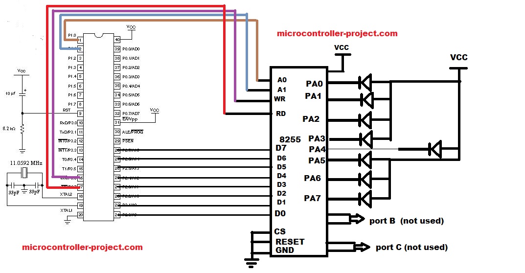
The circuit is very easy. Connect port 2 of 8051 with data pins of 8255. Make CS(chip select) and RESET pins of 8255 ground. Connect A0 with port 1 pin 0 of 8051 microcontroller, and A1 with port 1 pin 1. Connect WR(write) pin of 8255 with port 3 pin 6. Connect RD(read) pin of 8255 with port 3 pin 7. The circuit diagram is given below.
- P2=0xF0 -> Making upper four nibbles of port A of 8255 high and lower low.
- P2=0x0F -> Making lower four nibbles of port A of 8255 high and upper low.
These upper two conditions makes leds to look like blinking. The delays between the conditions are very important. They are used to make leds retain in certain condition for some time for example 0xF0 should retain on port A for some time and then switch to 0x0F. If you dont use delays in these two conditions you will be unable to see leds blinking. The program executes so fast that it becomes so hard to identify whats going on.
Filed Under: 8051, Electronic Projects, Microcontroller Projects


Questions related to this article?
👉Ask and discuss on Electro-Tech-Online.com and EDAboard.com forums.
Tell Us What You Think!!
You must be logged in to post a comment.