Last 5-6 years, I am using MikroC Pro compiler for creating PIC experiments like LED interfacing, LCD interfacing. Earlier I tried MPLAB cross compiler also. I would like to share my experiences with readers.
As part of my job, I was supposed to create projects for Microchip PIC 16F877a. I downloaded MPLAB software. As our natural habits, we do not want to purchase license due to small project size. I installed MPLAB and did some coding. This worked well for 4 months. After six to twelve months I could not use MPLAB software due to other job priorities.
When after the break I wanted to use MPLAB again on my same machine, it was giving lot of errors and not operating for small projects. One reason, I thought could be that my trial period was over. I downloaded another version of MPLAB, but till date it was not running on my machine properly. I removed completely and re-installed fresh installation. Still giving problem. At one moment I decided to move to Mikro C pro compiler. Of course, how to convince clients for MikroC Pro is very challenging job, which I am facing even now.
Let’s learn MikroC Pro for PIC. My PIC controller is P16F877A. I will explain simple LED interfacing with P16F877A.
1)You can download Mikro C Pro for PIC cross compiler from website:
http://www.mikroe.com/mikroc/pic/
It is demo 6.6.1 version and included demo license enables up to 2K of program words of FREE output code.
Our student or novice projects can be executed by 2k HEX file size.
You create your own working directory to save your work. For example I created c:PIC_projects> directory in the C: drive of my computer.
2)Double click on MikcroC pro icon on the desktop and you will get Fig1 IDE of Mikroc Pro cross compiler. I hope, you understand why I am saying it is a cross compiler. Because I am running this compiler on Pentium computer but I want to generate HEX code for PIC 16F877a microcontroller. This HEX code I will transfer on PIC board for execution using PICkit2 programmer. This is reason that why these cross compilers keep asking us “what is your target device?”.
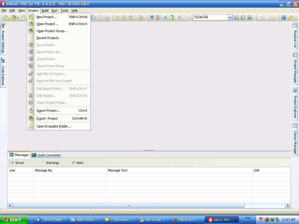
Fig. 1: Image Showing IDE of MIkroC Pro for PIC
3)After selecting Project menu, compiler ask you whether you want to open old project or you want to create New Project or you want to see “Recent Projects”. Click on New project, compiler is displaying wizard window, This “New Project Wizard” is going to help you for selecting Target microcontroller of your development and frequency of your target microcontroller. This wizard is going to help for adding project files. Fig 2 shows this screen.
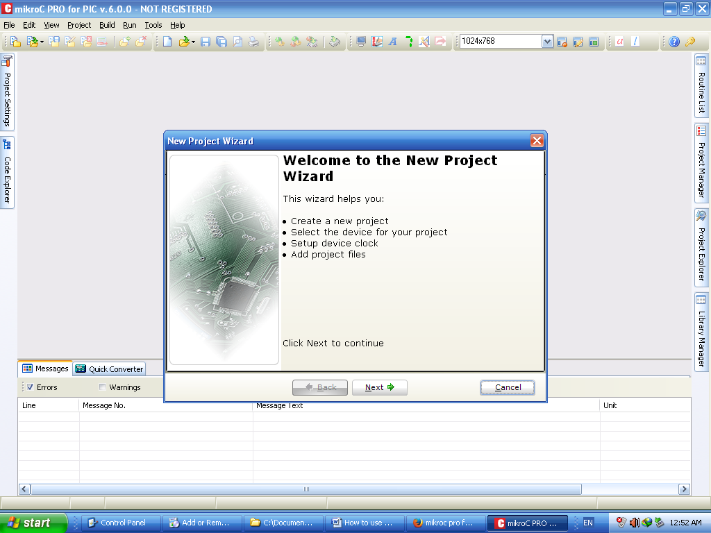
Fig. 2: Image Showing Output When You Click “Output’ in “Project” menu
4) You have to click “Next” button where green arrow is there. Fig 3 shows step 1 of project creation and MikroC is showing default PIC Microcontroller “P18F45K22” and Pull down menu to change this target and compiler is also asking Project name and path (where you want to save your first project).
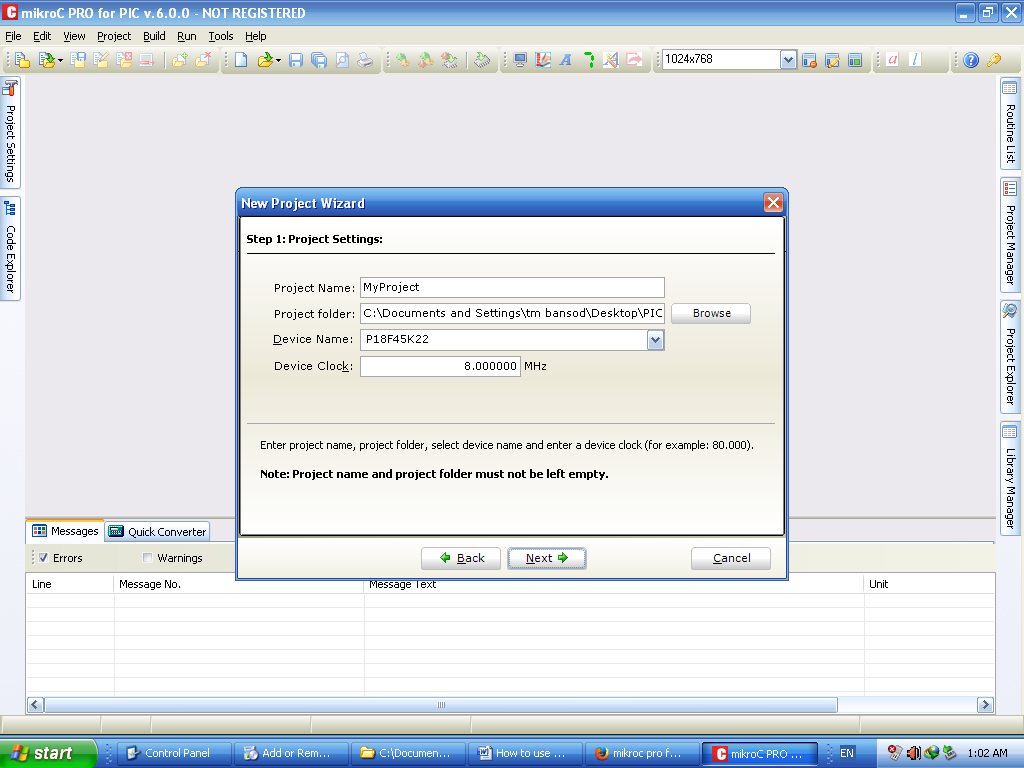
Fig. 3: Picture Showing Image Settings For Target Selection and Project Name
5) Fig 4 shows how to browse for saving your project. I suggest you create your own_name directory to save project. It is not a good idea to save your own project in the examples folder of compiler. In fig 4 you can see that I selected “LED” as a project name because I want to toggle LED and I am saving project in PIC_project directory in C: drive. Then you click on “Ok” button of Browse windows. You will come back to “New Project window” display window.

Fig. 4: Image Showing Open Browse Window for Project Creation
Page 1
6) We are going to select P16F877A microcontroller as target in MikcroC compiler. It is easy to learn and easily available in the market. Cost of this IC is from INR 150 to INR 250. It is 40 pin IC and having RA,RB,RC,RD,RE ports. Names of ports are different. Port RB,RC,RD are 8 pin long and port C is divided on both side of IC. Port RA is of 6 pins and three pins for Port RE. Fig 5 shows actual P16F877a DIP IC and it is also available in QUAD form also. We cannot do serial programming this IC and we need PIC Kit2 or PICkit 3 programmer which are easily available.
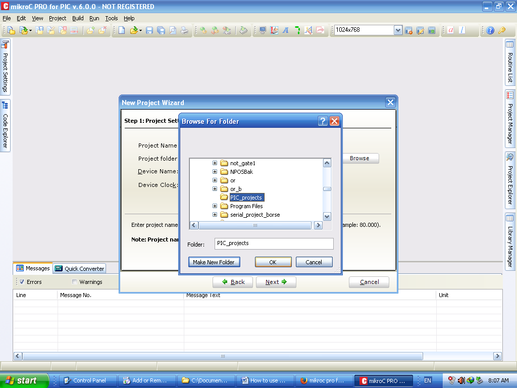
Fig. 5: Image Showing Project Selection from Browse Window
Fig. 6: P16F877A PIC Microcontroller DIP IC
Fig. 7: Diagrammatic Presentation of P16F877A PIC Microcontroller
Techical Specification of P16F877A
Following are technical specification of P16F877A:
|
Parameter Name |
Value |
|
Program Memory Type |
Flash |
|
Program Memory (KB) |
14 KB |
|
CPU Speed (MIPS) |
5 |
|
RAM Bytes |
368 bytes |
|
Data EEPROM (bytes) |
256 |
|
Digital Communication Peripherals |
1-UART, 1-A/E/USART, 1-SPI, 1-I2C1-MSSP(SPI/I2C) |
|
Capture/Compare/PWM Peripherals |
2 CCP |
|
Timers |
2 x 8-bit, 1 x 16-bit |
|
ADC |
8 ch, 10-bit |
|
Comparators |
2 |
|
Temperature Range (C) |
-40 to 125 |
|
Operating Voltage Range (V) |
2 to 5.5 |
|
Pin Count |
40 |
7) Again come to selection of target device, now you have to scroll target device from pull down menu. You carefully select P16F877A and change frequency from 8 MHz to 20 MHZ. Datasheet of P16F877A shows that it is working on 20 Mhz frequency. Fig 6 shows selection of microcontroller P16F877A. Then click on “Next” button.
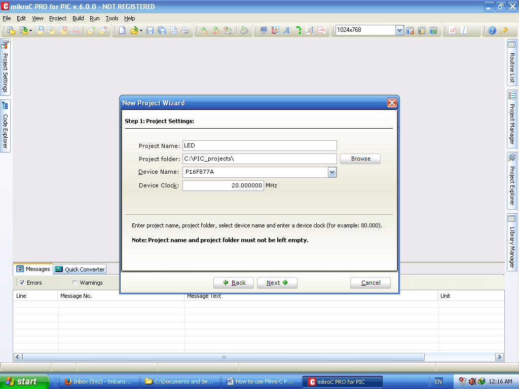
Fig. 7: Image Showing P16F877A Selection from Pull Down Menu
8)After Next button, MikcroC shows Fig 7, it is asking for source files name which You want to add in the project folder. Please remember “Project” is folder where we can include various files such as LED.C and some header file if required or any library file. Cross complier will use all these files to create HEX file.

Fig. 8: Compiler Needing Source Code File
9) I typed “led.c” as source file. My project name and source code file can be same or you can give any name and click on “Add” button. Now my led,c will become part of LED project. Click on the Next button. We will get Fig 8 shows how to add “led.c file name in project and click on “add” button.
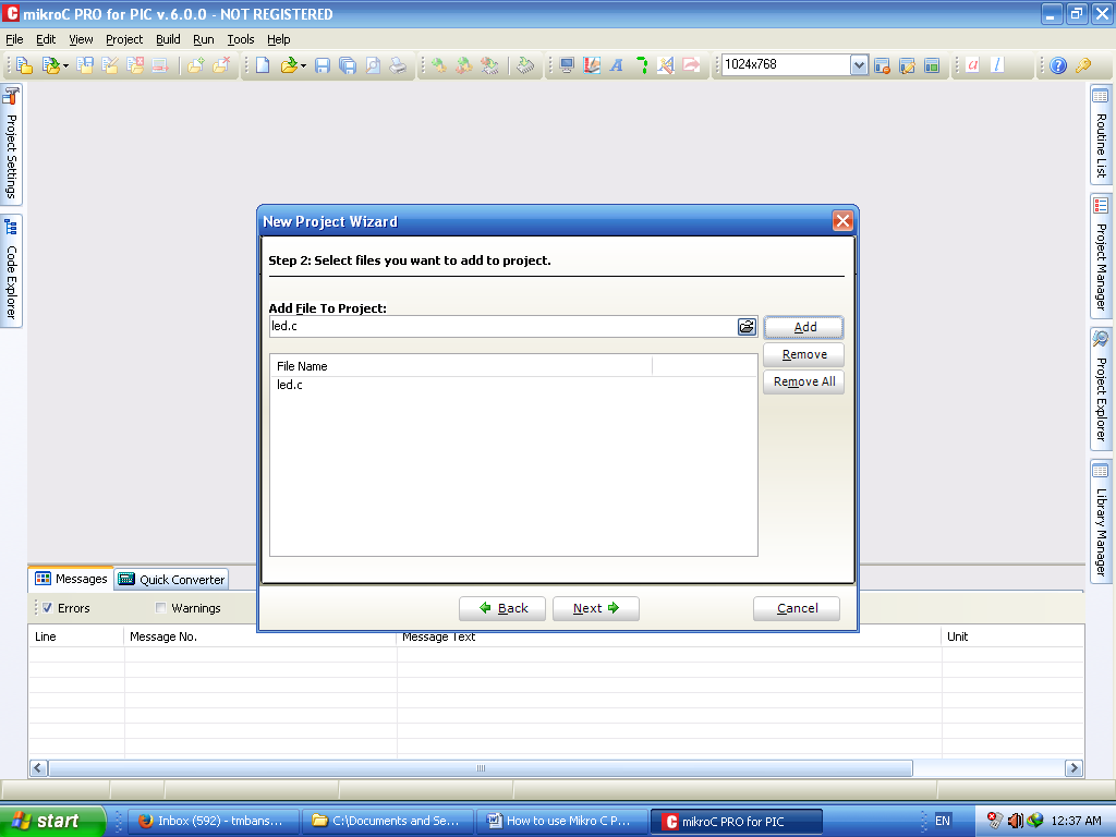
Fig. 9: Adding “led.c” Extension in Source File Name
10) One mechanism is whether you want to include Default All libraries and the other is “None Libaray” MikroC suggests that beginners should use default library. Due to libraries, you will get a lot of inbuilt functions from MikroC compiler. We will select “Include All” options. Click to Next button. Fig 9 shows two mechanisms of “include” library files.
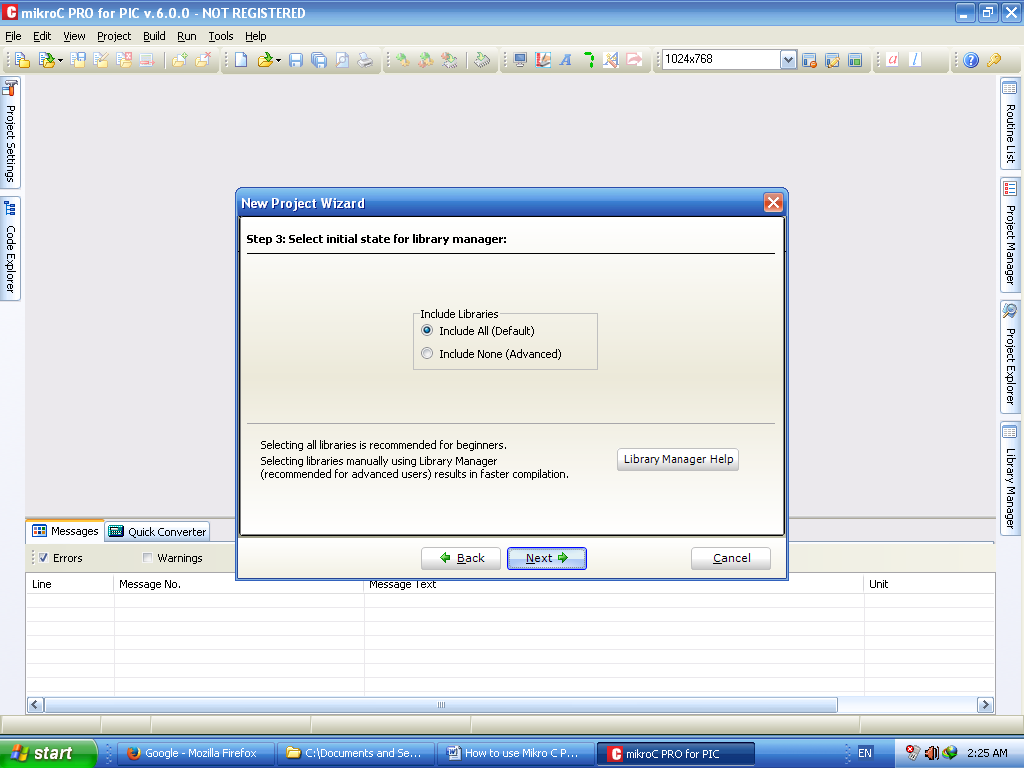
Fig. 10: Including Library Option in Project Creation
11)We have reached to step 4 of project creation, Fig 10 shows last screen of project creation. You click on “Finish” button and you will get code screen of IDE.
Fig. 11: Image Showing Finish Screen on Project Creation
page 2
12)Fig 11 shows void main() { } loop in the IDE. This shows you are free to type your code here. I want to toggle (ON/OFF all port lines of P16f877A microcontroller).
Fig. 12: Image Showing Last Screen of Project Creation Where Code can be Typed
13)Now to toggling LED of I/O lines, we have to set direction of IO lines first. There are TRISA, TRISB, TRISC such registers in P16f877A and when you initialize this register by “0” direction of IO line will be “output”. As LED is output device (we are displaying means giving voltage to it). We have to use TRISA=0 in the code. Fig 12 shows code for LED displaying.
Fig. 13: Image Showing MikroC Pro Edit Screen
14) You can see below code is very simple to understand, compiler is giving error for RA, RB, RC words for port. You can use PORTA, PORTB names for PORT.
Whole code is like this:
|
void main() {
TRISA = 0; // set direction to be output TRISB = 0; // set direction to be output TRISC = 0; // set direction to be output TRISD = 0; // set direction to be output TRISE = 0; // set direction to be output
do { PORTA = 0x00; // Turn OFF LEDs on PORTA PORTB = 0x00; // Turn OFF LEDs on PORTB PORTC = 0x00; // Turn OFF LEDs on PORTC PORTD = 0x00; // Turn OFF LEDs on PORTD PORTE = 0x00; // Turn OFF LEDs on PORTE Delay_ms(1000); // 1 second delay
PORTA = 0xFF; // Turn ON LEDs on PORTA PORTB = 0xFF; // Turn ON LEDs on PORTB PORTC = 0xFF; // Turn ON LEDs on PORTC PORTD = 0xFF; // Turn ON LEDs on PORTD PORTE = 0xFF; // Turn ON LEDs on PORTE Delay_ms(1000); // 1 second delay } while(1); // Endless loop
} |
15)After typing whole above code in the editor screen of MikroC pro. You can click on “Build” menu. Fig 13 shows “Build” options of menu, after typing code to create HEX file click on “Build”. This build option is compiling code and shows error also. If you have done some syntax based error, compiler shows in different window.
Fig. 14: Image Showing Build Options in Menu
16)Since you have built your code correctly, now the interesting part is to observe what the files are which are created by compiler in your directory. Fig 14 shows different files created in my “PIC_projects directory. You will observe that compiler gives me HEX file, ASM file, C file, LOG file. You have to program P16F877A microcontroller using PICKit2 Programmer.
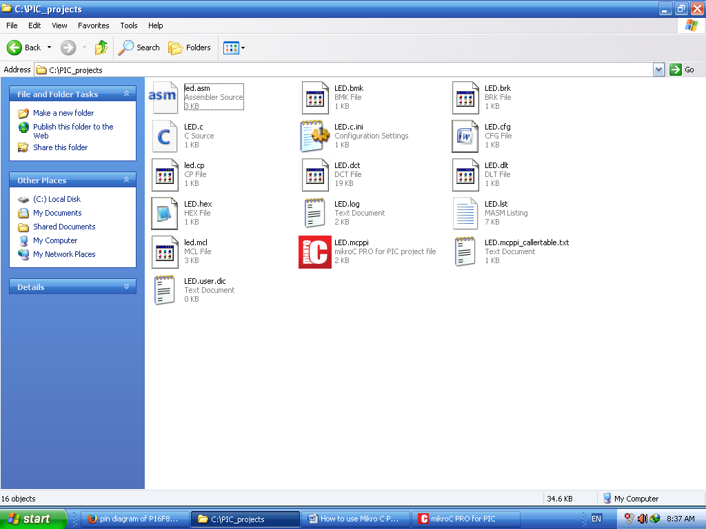
Fig. 15: Image Showing Project Directory PIC_Project
Fig 14 My project directory PIC_Project: see different files, find out what is meaning of these files as homework. You can take help of Google uncle.
17)I think debugging of code is a separate topic of research for P16f877A.
Filed Under: Articles
Log in to leave a comment:
Lost your password?
Don't have an account? Register here