In the previous tutorial VHDL tutorial, we designed an 8-bit parity generator and 8-bit parity checker circuits using VHDL.
(If you are not following this VHDL tutorial series one by one, you are requested to go through all previous tutorials of these series before going ahead in this tutorial)
In this tutorial,
- We shall write a VHDL program to build 3×8 decoder and 8×3 encoder circuits
- Verify the output waveform of the program (digital circuit) with the truth table of these encoder and decoder circuits
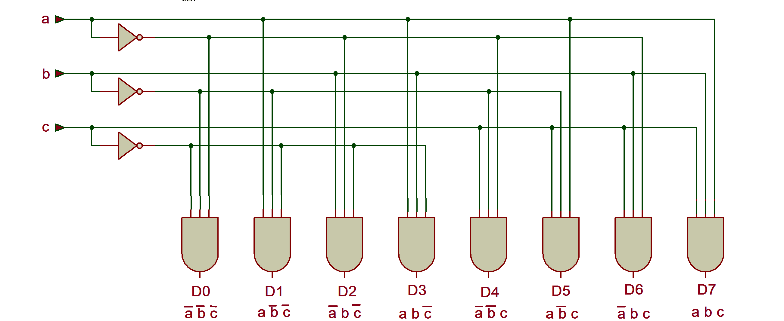
3×8 Decoder circuit
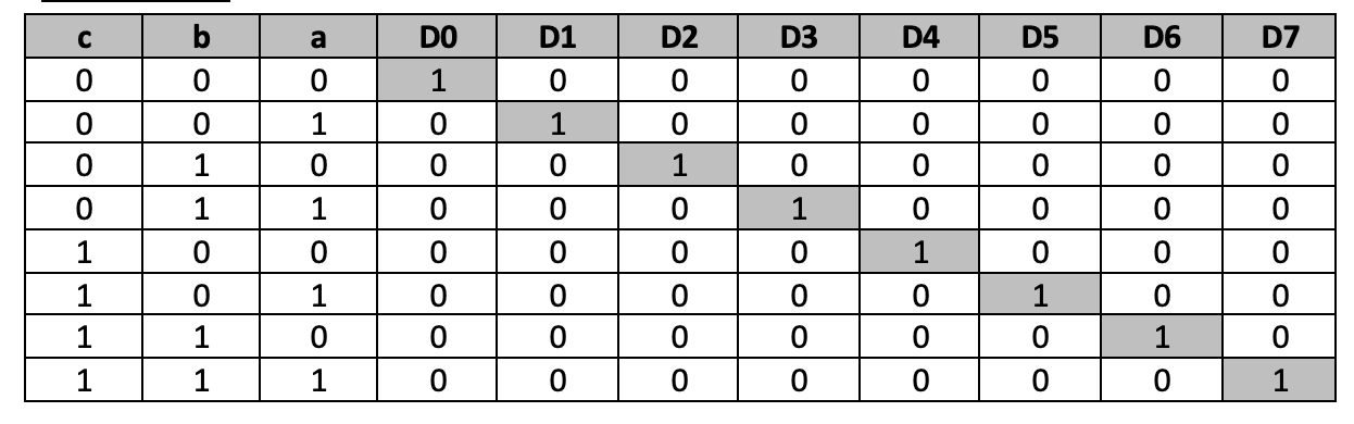
Truth Table
 Now we shall write a VHDL program, compile it, simulate it, and get the output in a waveform. Finely, we shall verify those output waveforms with the given truth table.
(Please go through step by step procedure given in VHDL-tutorial 3 to create a project, edit and compile the program, create a waveform file, simulate the program, and generate output waveforms.)
In previous tutorials, we had used either a data-flow modeling style or structural modeling style. But this time, we shall use a 3rd style that is the behavioral modeling style. Behavioral modeling style is useful in representing sequential digital circuits. The decoder is not a sequential digital circuit, but it will be easier to build this circuit using behavioral style.
VHDL Program
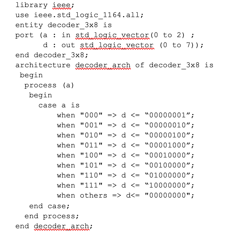 (To know more and get more details about VHDL program(s), please go through the first two tutorials, VHDL tutorial 1 and VHDL tutorial 2 of these series.)
Next, compile the above program – create a waveform file with all inputs and outputs listed – apply different input combinations – save the waveform file, and finally, simulate the project. You will get the following result.
Simulation Waveform
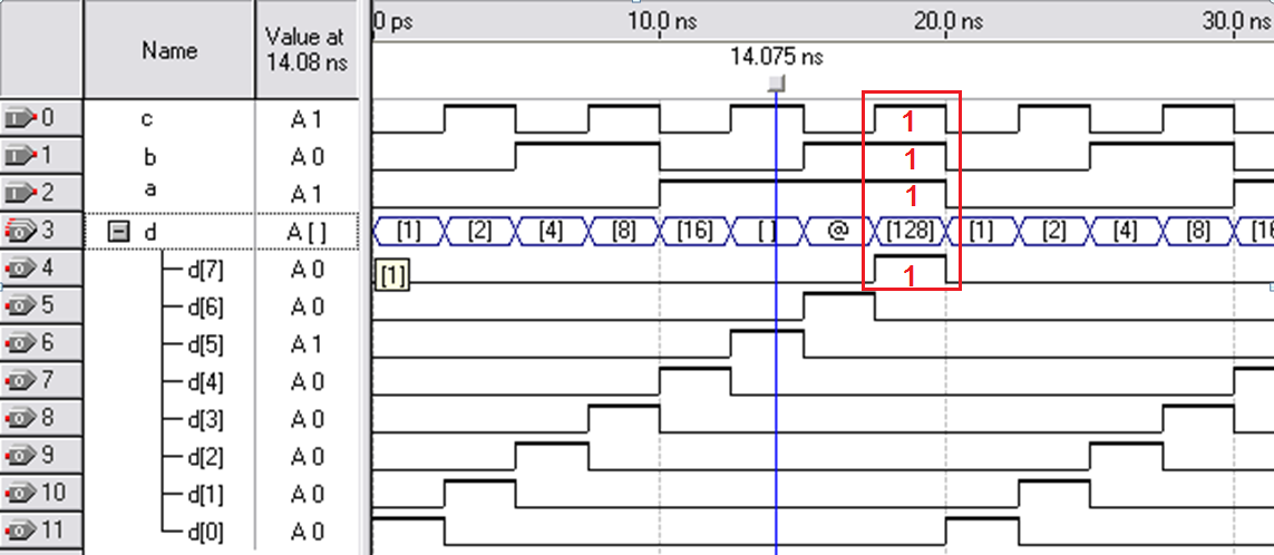 One can easily verify D0-D7 output, that is, at a time, only one output is high, and all others are low as per given input A0-A1-A2 combinations from “000” to “111”.
Now let us build an 8×3 encoder circuit
8×3 encoder circuit
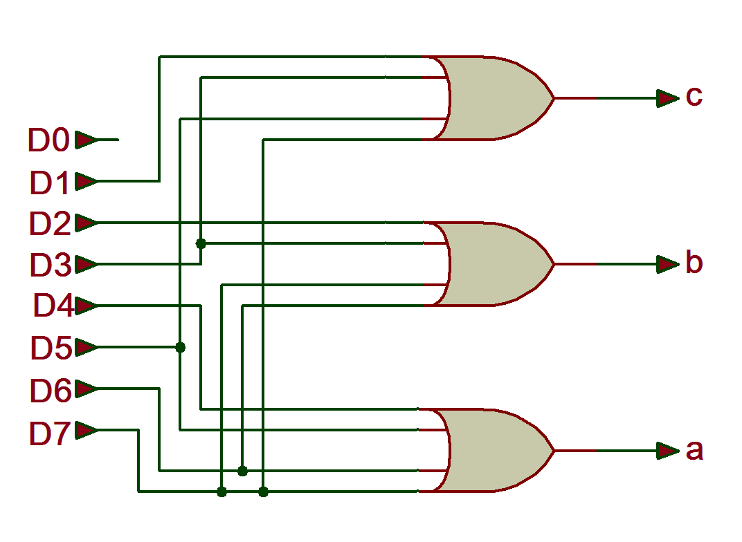
Truth Table

VHDL program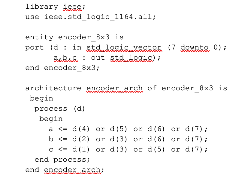 Simulation waveforms
As shown in the figure, the input-output waveforms look similar to the decoder because the encoder is just the reverse of the decoder. The input becomes output and vice versa. Here in the given figure, one case is highlighted when D7 input is ‘1’ all outputs a = 1, b=1, and c=1. You can verify other combinations from the truth table.
In the next tutorial, we shall design 8×1 multiplexer and 1×8 de-multiplexer circuits using VHDL.
Filed Under: Tutorials, VHDL, VHDL
Log in to leave a comment:
Lost your password?
Don't have an account? Register here