This project demonstrates the operation and interfacing of a servo motor, where the control signals for the rotation of the motor are provided by LPC1768 (ARM Cortex M3). The servo arm rotation is controlled by a potentiometer interfaced to the ADC of LPC1768. Starting from 0° as initial position it rotates to 180° as the potentiometer rotated from one position to other. For ADC interfacing with LPC1768 refer this article. For basic concepts and know-how of a servo motor, refer to the article Servo Motor. For setting up the Environment for the development of ARM cortex M3 is well discussed in this article.

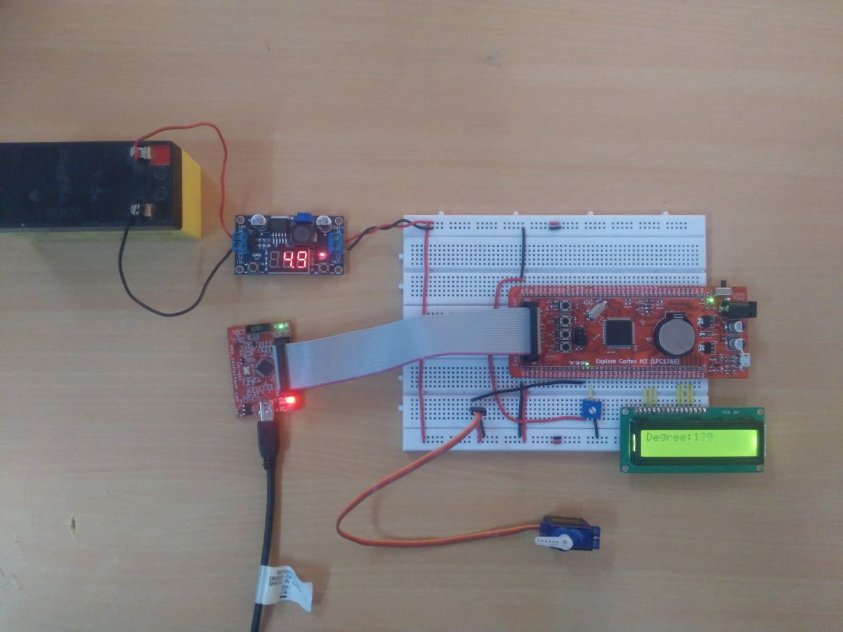
Fig. 1: Interfacing Servo Motor With LPC1768 Prototype
Servo motors find huge applications in industries in the field of automation, control & robotics. The servo motors are well known for their precise control and work on the principle of servo mechanism. The servo motors can be made to run at precise angle using PWM. The PWM (pulse width modulation) is the basic working principle behind a servo motor (For more details about PWM refer Phase correct PWM mode). The servo motor is controlled by feeding pulse width modulated (PWM) signal at the control wire of the servo motor. For more details about the programming of PWM in LPC1768 refer this article.
A Servo motor has three wire terminals : two of these wires are to provide ground and positive supply to the Servo DC motor, while the third wire is for the control signal. These wires of a servo motor are color coded. The servo motor can be driven only when PWM (pulse width modulated) signals are provided to the control terminal.
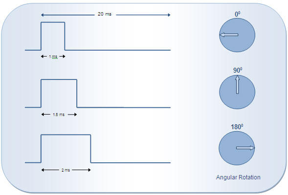
The total pulse duration for a typical servo motor should be of 20 milliseconds. The on-time duration of the control signal varies from 1ms to 2ms. This on-time variation provides angular variation from 0 to 180 degree. Also refer Servo motor control using 8051.

Fig. 2: Total Pulse Duration Of typical Servo Motor With Angular Variation
According to the above diagram, desired angular position can be calculated by simple interpolations. For example, if the servo motor should be positioned at 45° angle, the desired output control pulse can be obtained as follows:
180° angular displacement is achieved by the pulse duration = 1 ms
1° angular displacement is achieved by the pulse duration of = 1 /180 ms
45° angular displacement is achieved by the pulse duration of = (1/180) x 45 = 0.25 ms
So total on-time pulse will be = 1ms + 0.25ms =1.25 ms
Please note that the on-time duration of the control signal may vary based on the manufacturer or certain other conditions. Therefore it is imperative that the on-time pulse for 0° and 180° positions must be obtained (either from the datasheet or by hit-n-trial) before using a servo motor for an application. The servo motor used here moves to 0° at 0.74 ms pulse.
Circuit Description:
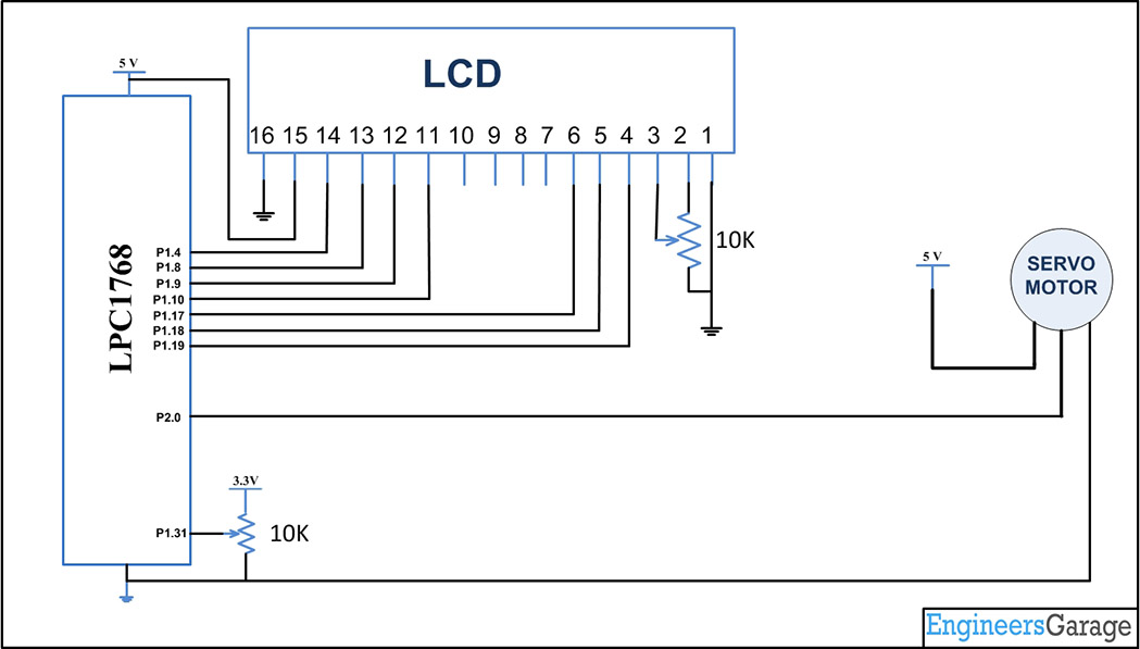
In the circuit, Port P2.0 is defined as output pin to provide the PWM in the control pin of the stepper motor.. The other two motor leads are connected to the VCC (5V) and the GND respectively. The POT is connected to the ADC input P1.31 for the speed control of the Stepper motor. LCD is also interfaced to show the degree of the servo.
Programming Steps:
1. Calculate the on-time duration for 1° angular displacement.
2. Read the ADC value from the potentiometer.
3. Set the pin high at which control terminal of the servo motor is connected.
4. Call the mapping function which maps ADC values to the corresponding ON time in pulse.
5. By using the above ON time start the PWM in the output pin.
6. Map the ADC values to 0 to 180, which is used to display in LCD.
7. Repeat the steps from 4 to 7 continuously to send a train of pulses.
Create a project using Keil uvision4 for LPC1768 Microcontroller:
In this section, we will start creating a project in Keil MDK we have already installed Keil µVision and Co-MDK Plug-in + CoLinkEx Drivers required for the CoLinkEx programming adapter. You can start by downloading the project files and kick start your practical experiment.
Code Description:
Here the Library PWM.C is used to configure all the PWM functions and ADC is used as per the previous tutorial.
PWM_Init( CHANNEL_NUM, cycle );
PWM_Set( CHANNEL_NUM, cycle, offset );
PWM_Start( CHANNEL_NUM );
These are the functions used for our application. Here CHANNEL NUM macro defines 1.
offset = map(adc_result, 0, 4093, 74, 340);
The adc_result is mapped to get the output which gives the delay to the PWM function.
PWM_Set( CHANNEL_NUM, cycle, offset );
This is the function to set the PWM in the output pin. All the above codes will be in an infinite loop, whenever the POT is changed the corresponding ADC value will be changed and the new offset is calculated and the position is changed accordingly.
For more details on interfacing the LCD in 4 bit mode with LPC1768 refer this link.
Project Source Code
###The codes are linked in Description ###
Circuit Diagrams
Project Components
Project Video
Filed Under: ARM.
Filed Under: ARM.


Questions related to this article?
👉Ask and discuss on EDAboard.com and Electro-Tech-Online.com forums.
Tell Us What You Think!!
You must be logged in to post a comment.