Whenever we talk about any remote controlled home appliance, it’s obvious that it’s an Infra Red (IR) remote control. For example TV, music system, DVD player, AC, fan, air cooler etc any home appliance, is controlled by an IR remote. These remotes work on different IR protocols like RC5, RC6 (developed by Philips) or NEC etc. The principle of operation is, they will send one code to the appliance when any of the buttons is pressed. The code is actually series of bits (1’s and 0’s) in form of pulses. The pattern of pulses for 1 and 0, changes as protocol changes.
Decoding remote code means to identify the number associated with different buttons of given IR remote. For example, in normal TV remote, there are different buttons like digit 0 to 9, volume up-down, channel up-down, menu, arrow key buttons etc so many. So we have to find out which number is generated and sent to TV when a particular button is pressed.
This is not an easy task. First, you have to read the documentation for the protocol used in IR remote to get the information of the format of pulse pattern for digit 0 and digit 1. Then you have to capture the bit pattern on DSO. To do this -:
• First, make an IR sensor circuit on breadboard or general purpose PCB
• Connect the output of sensor to DSO
• Now point remote to sensor and press any button
• The bit pattern appears in form of pulses
• Analyse the pulses and bit pattern and note down digit 0 and digit 1 in sequence
• From these digits, you can find a code number for pressed button
This is the procedure to get the code for only 1 button of any 1 remote only. Think about decoding codes for all the buttons in 1 remote. And next, think of decoding codes of any IR remote.
Sounds very tedious and difficult? What if I say, you just point any IR remote to one circuit, press any button and the code (number) is directly displayed on LCD? Surely you may ask, is it possible?
The answer is yes! And the answer is this project. Using this project you can get the code for any button of any IR remote. This is possible with the help of arduino. The IR Remote library for arduino can be used for this purpose. This library is readily available on the internet as an open source. With the use of this library, one can easily decode the codes of any IR remote. just he needs an IR sensor and any arduino board.
Here in this project, I have used TSOP1738 IR sensor and Arduino UNO board. It uses 16×4 LCD to display the decoded code – the number for pressed button on IR remote.
I think you are getting too much excited to build this project. So let us start building the project. First, see the circuit diagram followed by its description and its operation. In the last software program is given with necessary explanation and comments.
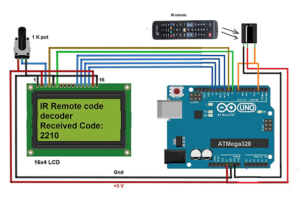
As shown in above figure there are only 3 major components Arduino board, LCD and IR sensor.
• IR sensor has 3 terminals. The 1st ground terminal is connected to the ground of arduino board. 2nd supply terminal is given 5 V supply from the board. The output terminal (3rd ) is connected to digital pin 7 as well as pin 2 of the board. Pin 2 is used as interrupt input pin (it is used to generate interrupt when IR sensor receives any code)
• LCD control pins Rs and En are connected to digital pins 8 and 9 of arduino board respectively. RW pin is connected to ground to enable LCD write
• LCD data pins D4-D7 are connected to digital pins 10 – 13. LCD backlight terminals 15 and 16 are connected to +5V and board ground respectively to turn ON backlight LED of LCD
• One 1 K pot is connected to Vee pin (3) of LCD as shown, to vary its contras
The snap given below shows necessary connections.

Fig. 1: Prototype of Arduino based IR Remote Code Decoder
CIRCUIT OPERATION
• When the circuit is given power supply from USB of host PC/laptop, arduino displays message on LCD as “IR Remote code decoder”. It also displays “Received code:” and then it waits to receive any code from the sensor.
• It continuously waits for any new code received by sensor
• Now when anyone points any IR remote towards sensor and press any button, the IR sensor receives the code and gives it to Arduino.
• As the code is received, pin 2 gets an interrupt. So arduino decodes the code and this button code (means the number) is displayed on LCD as “Received code: XXXXXXXX”
• Every time a new button is pressed, the new code is displayed on LCD.
• If you change the remote and press any button, its code will be displayed on LCD.
This means using this circuit, you can get (decode) the code for any button of any IR remote.
SOFTWARE PROGRAM
The IR remote code decoding is possible due to the arduino IR Remote library. This library is open source and readily available on the internet. You can easily download this library. Just copy the library into the root directory (folder) of arduino (C:arduino-1.6.7libraries). Now you can get this library from arduino IDE software as sketch (menu) -> include library -> IRRemote.
Complete functionality of project is because of the program downloaded into arduino board microcontroller ATMega328. The program is the soul of the project. The program (also known as sketch) is written and compiled in arduino IDE software tool. And it is burnt (embedded) into ATMega328 using built in software programmer tool AVRISP MK-II through the USB port.
Project Source Code
###
#include <IRremote.h> // library for IRRemote functions #include <LiquidCrystal.h> // library for LCD functions int IRpin = 7; // pin for the IR sensor int intr_pin = 2; // interrupt pin IRrecv irrecv(IRpin); // configure IR pin decode_results results; // decoded codes as result unsigned long int prev_code; // save previous code LiquidCrystal lcd(8, 9, 10, 11, 12, 13); void setup() { Serial.begin(9600); // initialize serial port //////////// print message on serial monitor ////////////////// Serial.println("IR remote code decoder using interrupts"); irrecv.enableIRIn(); // Start IR receiver //////////////// attach interrupt to pin 2 with ISR //////////// attachInterrupt(digitalPinToInterrupt(intr_pin), receive_code, CHANGE); lcd.begin(16,4); // configure LCD and lcd.clear(); lcd.print("IR Remote code"); // display initial message lcd.setCursor(0, 1); lcd.print("Decoder"); lcd.setCursor(0, 2); lcd.print("Received Code:"); } void loop() { delay(200); // wait for irrecv.resume(); // new received code } void receive_code() { if(irrecv.decode(&results)) // when code is received { if(prev_code != results.value) // if its new code { lcd.setCursor(0,3); lcd.print(results.value); // display it on LCD prev_code = results.value; // and save it } } }###
Circuit Diagrams
Project Video
Filed Under: Electronic Projects
Filed Under: Electronic Projects
Log in to leave a comment:
Lost your password?
Don't have an account? Register here