Measuring the voltage of your solar panel, ups, and other daily use batteries consumes a lot of time. Grabbing multi-meter, opening the battery boxes, and touching both the multi-meter leads to terminals of the battery takes some effort. How about developing an efficient IoT system through which you can see the status of your battery on your desktop and mobile web browsers?
Let’s start and do this DIY project since we will develop an IoT system that can monitor battery status and update us on our browser. We will need some circuit/device/controller which can effectively measure voltage.
A WiFi device which can connect to our local home WiFi takes voltage reading from the controller and updates the end-user about the current battery level. For this purpose, I decided to use the NodeMCU WiFi module in the project. It can not only work as a controller, but also it can connect itself to a WiFi network like a server or client. The battery monitoring circuit is a traditional voltage divider circuit. I am going to measure 12-volt batteries. The circuit can be modified to measure 24-volt batteries and even more 48 volts parallel battery clusters.
Voltage divider working and calculations
NodeMCU is a tiny device; it works on 3.3 volts. Since it is working on 3.3 volts, its pins can source and sunk 3.3 volts only. A voltage greater than 5 volts may blow the pin or fry the NodeMCU. In our case, we want to measure a 12-volt battery, and NodeMCU ADC (analog to digital converter) can only accept 3.3 volts. We need to play smartly here. We will divide the voltage between two resistors and measure the only voltage across one resistor, and the remaining resistor voltage will be calculated mathematically. A typical voltage divider circuit and formula are given below.
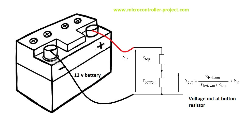
Voltage divider with battery circuit
Now let’s calculate the values for Rtop and Rbottom. Here we need some important considerations to be taken seriously.
- Low ohm resistors can sunk much current, and wires could be heated instantly. Consequently, wires can meltdown in seconds. So always use a sufficient amount of resistors for bigger ampere-hour batteries. I selected one resistor Rbottom to be 10k ohm.
- During charging, the battery voltage can increase to 18 volts. For example150 a watt solar panel outputs 17 volts at 6 amperes during full sun. The output voltage can even reach above 18 volts. The solar charge controller also outputs voltage approximately equal to 15 volts to charge the batteries.
Formula Calculations
I will measure the voltage across Rbottom, and I decided its value randomly to be 10k ohm. We know Vout can be up to a maximum of 3.3 volts since NodeMCU works and accepts a maximum of 3.3 volts at its I/O pins. Vin is 18 volts when the battery is charging. Now we can find Rtop.
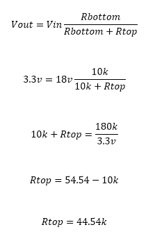
Voltage divider resistance value calculation
If 18 volts are at the battery side, it will be divided across resistors, 3.3 volts drop at 10k resistor and remaining 14.7 volts drop at 44.54 k resistor. 44.54 k ohm resistor is not available in the market I am going to use the one above this rating and easily can be found from any electronics shop 47 k ohm resistor. If the battery is not charging and supplying 12 volts, what will be the voltage drop across resistors? Let’s calculate it
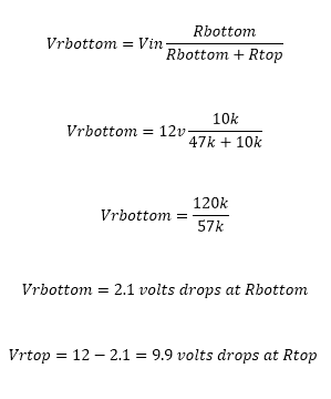
The voltage drop across resistance of voltage divider circuit
It’s obvious from the above discussion that the voltage across Rbottom will not exceed 3.3 volts now. I hope it makes sense to readers about the calculations. The question now is how the 3.33 volts is converted to 12 volts by NodeMCU or how from 3.33 volts we can predict that at the battery side, the voltage is 12 volts. Well, a little more mathematics is involved here. Since the resistor values are fixed, we can calculate the voltage ratio across the resistors with respect to the source and use it in code for actual voltage at the source. How the ratio is calculated is below.

Voltage divider ratio calculation
Two cases are given above when the source is at 18 volts and when the source is at 12 volts in both the cases, the ratio comes out to be a constant value. This ratio is utilized in code for predicting the actual source/battery voltage. The ratio is multiplied with voltage at Rbottom for the actual voltage value.
The project circuit diagram is given below. I am using the ADC0 channel of NodeMCU to measure the battery voltage. Both the battery and NodeMCU power must be grounded together to complete the circuit. Its most common mistake will be measuring the voltage that both grounds are not grounded together. If the NodeMCU ground is not taped with the battery ground, the adc0 pin will become a floating pin and start reading floating values.
The project circuit diagram is given below. I am using the ADC0 channel of NodeMCU to measure the battery voltage. Both the battery and NodeMCU power must be grounded together to complete the circuit. Its most common mistake will be measuring the voltage that both grounds are not grounded together. If the NodeMCU ground is not taped with the battery ground, the adc0 pin will become a floating pin and start reading floating values.
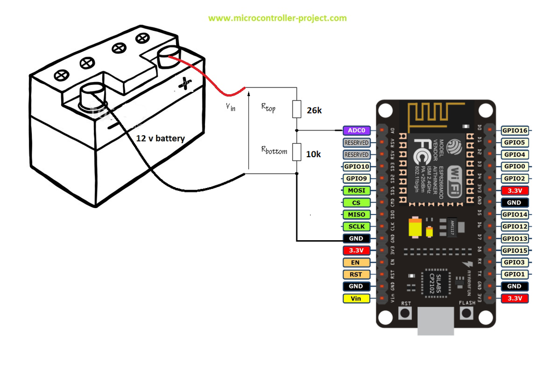
Battery voltage monitoring with NodeMCU
After you completed the circuit, it’s time to move on to code. Code is written in Arduino IDE. I used the ESP8266WiFi.h library in the code, so first, please make sure you installed this library in your Arduino library folder. If it’s not present, download it from GitHub, and install it first. Then enter the SSID and password of the WiFi network to which you want your NodeMCU to be connected. Most probably, it will be your home WiFi. So enter the SSID and password. Now upload the code in NodeMCU. Before uploading, make sure you selected the right board from Arduino boards. If NodeMCU does not appear in your board’s drop-down menu, import its link from its manager and install its necessary files. You can find many tutorials on the internet about how to install NodeMCU support for Arduino IDE.
|
After uploading the code, you have to do a little one-time complex work. Open Arduino serial monitor. As soon as you open it, you will see the NodeMCU server starting and your WiFi assigning an IP to your NodeMCU. This IP is essential. You have to enter this IP in your mobile or desktop browser to see the battery status. Suppose you do not see any message on the serial monitor. Check for serial monitor communication speed. It must be 9600 bps. Could you change it to 9600? If you still do not see anything, the code might not be uploaded correctly, or the board is disconnected. Check for possible errors. Once your router allows the IP to the NodeMCU, it will remain the same all the time. I hope so 😀
|
|

|
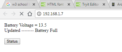
As soon as you hit the assigned IP in your browser, you will see the battery status page and a button. Press this button to get the updated temperature whenever you want.
Note: Nodemcu and your client mobile or desktop on which you want to view the voltage must be connected to the same WiFi. If your server-nodemcu and client-mobile or computer, laptop, etc., are connected to different networks, you can not view anything after hitting the IP. |
battery voltage monitor over WiFi
|
This is a base project. Furthermore, developments can be made to the project. Like data can be sent to the remote website to be displayed in real-time on web pages. An alert can be generated when voltage is low. LEDs or LCD can be connected to NodeMCU for on-spot status view.
To learn about other ways to measure battery voltage take the below tutorial. The tutorial is about measuring batteries when they are connected in series and parallel combinations.
Download the project code. The folder contains the project .ino file. Please provide us your feedback on the project. If you have any queries or questions, write them below in the comments section.
You may also like:


Filed Under: Electronic Projects, ESP8266.

Questions related to this article?
👉Ask and discuss on Electro-Tech-Online.com and EDAboard.com forums.
Tell Us What You Think!!
You must be logged in to post a comment.