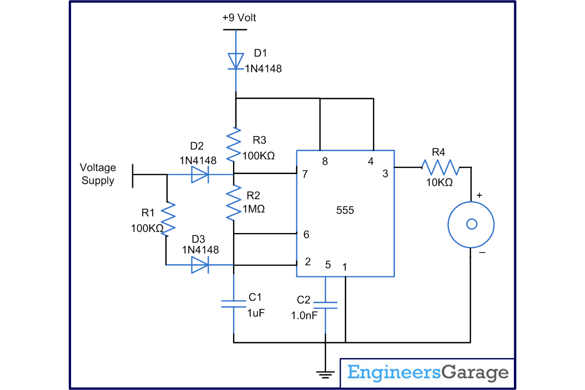
Sometimes there is need of devices which should intimate us when power goes off, so that we could switch off our devices if they are battery operated or they are getting power from some other limited source [such as for computer using UPS(uninterrupted power supply)]. This project can solve our purpose and can intimate us if power supply fails. This circuit has a 555 timer at its heart and following components that aid its working:
1. 1N4148 Diodes
2. Resistors in the range of Kilo and Mega Ohms.
3. Capacitors at the range of Micro Farads and Nano Farads.
4. A 9volt battery taking care of the power supply of the circuit.
The circuit of this project uses a 555 in astable mode producing a frequency of about hertz, by using resistors of 100k as R1, 1M? as R2 and capacitor C1 of 1 micro farad. What makes this circuit different is the diodes connected at pin7 and pin2 from voltage supply. When supply is present at these diodes they become forward biased and supply some extra voltage at pin7 and pin2 and consequently circuit does not work. Pin 7 and pin 2 work only when voltage at them is two- third and one-third of Vcc (here 9Volts) respectively & do not work even at high voltage or low voltage. This concept is used in this circuit. When power supply fails to arrive at these diodes pin7 and pin2 functions normally circuit works and sounds buzzer. Even when power supply fails diodes have some work to do; they become reverse biased and does not allow current to flow in direction of power supply.
Circuit Diagrams
Project Components
Filed Under: Electronic Projects


Questions related to this article?
👉Ask and discuss on Electro-Tech-Online.com and EDAboard.com forums.
Tell Us What You Think!!
You must be logged in to post a comment.