Engineers Garage

  • Projects and Tutorials
    • Electronic Projects
      • 8051
      • Arduino
      • ARM
      • AVR
      • PIC
      • Raspberry pi
      • STM32
    • Tutorials
    • Circuit Design
    • Project Videos
    • Components
  • Articles
    • Tech Articles
    • Insight
    • Invention Stories
    • How to
    • What Is
  • News
    • Electronic Products News
    • DIY Reviews
    • Guest Post
  • Forums
    • EDABoard.com
    • Electro-Tech-Online
    • EG Forum Archive
  • Digi-Key Store
    • Cables, Wires
    • Connectors, Interconnect
    • Discrete
    • Electromechanical
    • Embedded Computers
    • Enclosures, Hardware, Office
    • Integrated Circuits (ICs)
    • Isolators
    • LED/Optoelectronics
    • Passive
    • Power, Circuit Protection
    • Programmers
    • RF, Wireless
    • Semiconductors
    • Sensors, Transducers
    • Test Products
    • Tools
  • EE Resources
    • DesignFast
    • LEAP Awards
    • Oscilloscope Product Finder
    • White Papers
    • Webinars
  • EE Learning Center
    • Design Guides
      • WiFi & the IOT Design Guide
      • Microcontrollers Design Guide
      • State of the Art Inductors Design Guide
  • Women in Engineering

Real Time Clock with Temperature using Arduino

By Salman Khan


Real time clock is a digital clock which display real time on 16×2 LCD display. Here in this circuit we can also set alarm and time. The DS1307 serial real-time clock (RTC) is a low-power, full binary-coded decimal (BCD) clock/calendar plus 56 bytes of NV SRAM. Address and data are transferred serially through an I²C, bidirectional bus. The clock/calendar provides seconds, minutes, hours, day, date, month, and year information. The end of the month date is automatically adjusted for months with fewer than 31 days, including corrections for leap year. The clock operates in either the 24-hour or 12-hour format with AM/PM indicator. The DS1307 has a built-in power-sense circuit that detects power failures and automatically switches to the backup supply. Timekeeping operation continues while the part operates from the backup supply. It is assumed that the reader has gone through the project how to get started with the arduino and interface LCD with arduino.

Image of Arduino based Real Time Clock and Temperature Indicator showing date time and temperature

Fig. 1: Image of Arduino based Real Time Clock and Temperature Indicator showing date time and temperature

Image of Arduino based Real Time Clock and Temperature Indicator designed on Breadboard

Fig. 2: 

Image of Arduino based Real Time Clock and Temperature Indicator

Image of Arduino based Real Time Clock and Temperature Indicator designed on Breadboard

Fig. 3: 

Image of Arduino based Real Time Clock and Temperature Indicator designed on Breadboard

Image of Arduino based Real Time Clock and Temperature Indicator designed on Breadboard

Fig. 4: Image of Arduino based Real Time Clock and Temperature Indicator designed on Breadboard

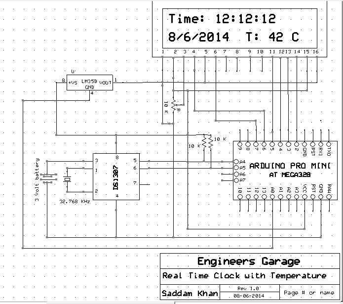
Block Diagram & Components Used

In this circuit pin D5,D4,D3,D2 of Arduino connected to the data pins D4,D5,D6,D7 of 16×2 LCD display respectively and digital pin D6 and D7 of Arduino connected to the command pins RS and En of 16×2 LCD display respectively. And serial data SDA and clock SCL pin of ds1307 connected to Analog pin A4 and A5 of Arduino respectively. In this clock the RTC is used in 24 hour mode which gives accurate time and can be displayed on LCD through Arduino. The Arduino continuously reads the data from the RTC. Program continuously read the data from ds1307 and show it on display. This system shows date, month, year and time.

And in this circuit a temperature circuitry is also add which shows Temperature on LCD display in degree Celsius. For read temperature LM35 sensor is used. This sensor is directly connected to Analog pin A0. After reading the A0 pin some easy calculation is applied and we get almost accurate temperature on the 16×2 LCD display.

Block Diagram of Arduino based Real Time Clock and Temperature Indicator

Fig. 5: Block Diagram of Arduino based Real Time Clock and Temperature Indicator

Components Used:

1.     Arduino Pro mini

2.     Ds1307

3.     Lm35

4.     16X2 Liquid Crystal Display

5.     Connecting wires.

Project Source Code

###


// Code by JeeLabs http://news.jeelabs.org/code/
// Released to the public domain! Enjoy!
#ifndef _RTCLIB_H_
#define _RTCLIB_H_
// Simple general-purpose date/time class (no TZ / DST / leap second handling!)
class DateTime {
public:
    DateTime (uint32_t t =0);
    DateTime (uint16_t year, uint8_t month, uint8_t day,
                uint8_t hour =0, uint8_t min =0, uint8_t sec =0);
    DateTime (const char* date, const char* time);
    uint16_t year() const       { return 2000 + yOff; }
    uint8_t month() const       { return m; }
    uint8_t day() const         { return d; }
    uint8_t hour() const        { return hh; }
    uint8_t minute() const      { return mm; }
    uint8_t second() const      { return ss; }
    uint8_t dayOfWeek() const;
    // 32-bit times as seconds since 1/1/2000
    long secondstime() const;   
    // 32-bit times as seconds since 1/1/1970
    uint32_t unixtime(void) const;
protected:
    uint8_t yOff, m, d, hh, mm, ss;
};
// RTC based on the DS1307 chip connected via I2C and the Wire library
class RTC_DS1307 {
public:
    static uint8_t begin(void);
    static void adjust(const DateTime& dt);
    uint8_t isrunning(void);
    static DateTime now();
};
// RTC using the internal millis() clock, has to be initialized before use
// NOTE: this clock won't be correct once the millis() timer rolls over (>49d?)
class RTC_Millis {
public:
    static void begin(const DateTime& dt) { adjust(dt); }
    static void adjust(const DateTime& dt);
    static DateTime now();
protected:
    static long offset;
};
#endif // _RTCLIB_H_

###


Circuit Diagrams

Circuit-Diagram-Arduino-Based-Real-Time-Clock-Temperature-Indicator

Project Video


Filed Under: Electronic Projects
Tagged With: Arduino, time clock
 

Questions related to this article?
👉Ask and discuss on Electro-Tech-Online.com and EDAboard.com forums.


Tell Us What You Think!! Cancel reply

You must be logged in to post a comment.

HAVE A QUESTION?

Have a technical question about an article or other engineering questions? Check out our engineering forums EDABoard.com and Electro-Tech-Online.com where you can get those questions asked and answered by your peers!


Featured Tutorials

  • Introduction to Brain Waves & its Types (Part 1/13)
  • Understanding NeuroSky EEG Chip in Detail (Part 2/13)
  • Performing Experiments with Brainwaves (Part 3/13)
  • Amplification of EEG Signal and Interfacing with Arduino (Part 4/13)
  • Controlling Led brightness using Meditation and attention level (Part 5/13)
  • Control Motor’s Speed using Meditation and Attention Level of Brain (Part 6/13)

Stay Up To Date

Newsletter Signup

Sign up and receive our weekly newsletter for latest Tech articles, Electronics Projects, Tutorial series and other insightful tech content.

EE Training Center Classrooms

EE Classrooms

Recent Articles

  • What are the battery-selection criteria for low-power design?
  • Key factors to optimize power consumption in an embedded device
  • EdgeLock A5000 Secure Authenticator
  • How to interface a DS18B20 temperature sensor with MicroPython’s Onewire driver
  • Introduction to Brain Waves & its Types (Part 1/13)

Most Popular

5G 555 timer circuit 8051 ai Arduino atmega16 automotive avr bluetooth dc motor display Electronic Part Electronic Parts Fujitsu ic infineontechnologies integratedcircuit Intel IoT ir lcd led maximintegratedproducts microchip microchiptechnology Microchip Technology microcontroller microcontrollers mosfet motor powermanagement Raspberry Pi remote renesaselectronics renesaselectronicscorporation Research samsung semiconductor sensor software STMicroelectronics switch Technology vishayintertechnology wireless

RSS EDABOARD.com Discussions

  • Vco cadencd
  • DA14531 Bluetooth and Xamarin.
  • 7 segment display connections
  • Slope compensation ramp calculation for UCC38084
  • Parts storage / inventory best practices and organization

RSS Electro-Tech-Online.com Discussions

  • Confirming whether this circuit will work
  • How does a blinky/flashing ball work?
  • I've DESTROYED 3 piezo buttons :((((
  • Control Bare LCD With ATmega328p
  • Modify a digital clamp ammeter ?
Engineers Garage
  • Analog IC TIps
  • Connector Tips
  • DesignFast
  • EDABoard Forums
  • EE World Online
  • Electro-Tech-Online Forums
  • Microcontroller Tips
  • Power Electronic Tips
  • Sensor Tips
  • Test and Measurement Tips
  • 5G Technology World
  • About Us
  • Contact Us
  • Advertise

Copyright © 2022 WTWH Media LLC. All Rights Reserved. The material on this site may not be reproduced, distributed, transmitted, cached or otherwise used, except with the prior written permission of WTWH Media
Privacy Policy | Advertising | About Us

Search Engineers Garage

  • Projects and Tutorials
    • Electronic Projects
      • 8051
      • Arduino
      • ARM
      • AVR
      • PIC
      • Raspberry pi
      • STM32
    • Tutorials
    • Circuit Design
    • Project Videos
    • Components
  • Articles
    • Tech Articles
    • Insight
    • Invention Stories
    • How to
    • What Is
  • News
    • Electronic Products News
    • DIY Reviews
    • Guest Post
  • Forums
    • EDABoard.com
    • Electro-Tech-Online
    • EG Forum Archive
  • Digi-Key Store
    • Cables, Wires
    • Connectors, Interconnect
    • Discrete
    • Electromechanical
    • Embedded Computers
    • Enclosures, Hardware, Office
    • Integrated Circuits (ICs)
    • Isolators
    • LED/Optoelectronics
    • Passive
    • Power, Circuit Protection
    • Programmers
    • RF, Wireless
    • Semiconductors
    • Sensors, Transducers
    • Test Products
    • Tools
  • EE Resources
    • DesignFast
    • LEAP Awards
    • Oscilloscope Product Finder
    • White Papers
    • Webinars
  • EE Learning Center
    • Design Guides
      • WiFi & the IOT Design Guide
      • Microcontrollers Design Guide
      • State of the Art Inductors Design Guide
  • Women in Engineering